Transcription of Getting Started with the NI PCIe-1427 - National Instruments
1 Getting Started with the NI PCIe-1427 The NI PCIe-1427 (NI 1427) is a PCI Express (PCIe) image acquisition device. The NI 1427 supports Base configuration Camera Link-compatible cameras. This document describes how to install and configure the necessary hardware and software components to begin using the NI You Need to Get StartedYou need the following items to set up and use the NI 1427: NI 1427 image acquisition device Base configuration Camera Link-compatible camera MDR 26-pin Camera Link cable Computer running Microsoft Windows Vista/XP/2000 with at least one available PCIe slotNoteVisit and enter rdvisionvista for more information about National Instruments image acquisition device compatibility with Windows Vista. NI Vision Acquisition Software or later, which includes the NI-IMAQ driver software Optional software for developing applications: NI Vision Builder for Automated Inspection NI Vision Development Module LabVIEW LabWindows /CVI Microsoft Visual BasicOptional EquipmentNational Instruments offers a variety of products for use with the NI 1427, including the following: NI Camera Link I/O Extension Board for additional triggering, timing, and I/O (part number 779352-01) 15-pin cable assembly kits for connecting the NI 1427 to general purpose digital I/O (part number 190912-04)Refer to the National Instruments catalog, visit , or call the National Instruments office nearest you for more specific information about these DocumentationThe following documents contain additional information that you may find helpful.
2 NI PCIe-1427 User Manual Contains information about programming options, hardware functionality, and signal connections. NI Vision Acquisition Software Release Notes Contains information about new functionality, minimum system requirements, and installation instructions for the NI-IMAQ driver Started with the NI Measurement & Automation Explorer Help for NI-IMAQ Describes how to configure the NI-IMAQ driver software, NI image acquisition devices, and cameras using Measurement & Automation Explorer (MAX). NI-IMAQ Help Contains fundamental programming concepts for the NI-IMAQ driver software and terminology for using NI image acquisition InformationCautionThe following paragraphs contain important safety information you must follow when installing and operating the not operate the device in a manner not specified in the documentation. Misuse of the device may result in a hazard and may compromise the safety protection built into the device.
3 If the device is damaged, turn it off and do not use it until service-trained personnel can check its safety. If necessary, return the device to National Instruments for away from live circuits. Do not remove equipment covers or shields unless you are trained to do so. If signal wires are connected to the device, hazardous voltages can exist even when the equipment is turned off. To avoid a shock hazard, do not perform procedures involving cover or shield removal unless you are qualified to do so. Disconnect all field power prior to removing covers or the device is rated for use with hazardous voltages (>30 Vrms, Vpk, or 60 Vdc), it may require a safety earth-ground connection wire. Refer to the device specifications for maximum voltage of the danger of introducing additional hazards, do not install unauthorized parts or modify the device. Use the device only with the chassis, modules, accessories, and cables specified in the installation instructions.
4 All covers and filler panels must be installed while operating the not operate the device in an explosive atmosphere or where flammable gases or fumes may be present. Operate the device only at or below the pollution degree stated in the specifications. Pollution consists of any foreign matter solid, liquid, or gas that may reduce dielectric strength or surface resistivity. The following is a description of pollution degrees. Pollution Degree 1 No pollution or only dry, nonconductive pollution occurs. The pollution has no effect. Pollution Degree 2 Normally only nonconductive pollution occurs. Occasionally, nonconductive pollution becomes conductive because of condensation. Pollution Degree 3 Conductive pollution or dry, nonconductive pollution occurs. Nonconductive pollution becomes conductive because of the device and accessories by brushing off light dust with a soft, nonmetallic brush.
5 Remove other contaminants with a stiff, nonmetallic brush. The unit must be completely dry and free from contaminants before returning it to u must insulate signal connections for the maximum voltage for which the device is rated. Do not exceed the maximum ratings for the device. Remove power from signal lines before connection to or disconnection from the device. CautionNational Instruments measurement products may be classified as either Measurement Category I or II. Operate products at or below the Measurement Category level specified in the hardware specifications. National Instruments Corporation3 Getting Started with the NI PCIe-1427 Measurement Category1: Measurement circuits are subjected to working voltages2 and transient stresses (overvoltage) from the circuit to which they are connected during measurement or test. Measurement Category establishes standardized impulse withstand voltage levels that commonly occur in electrical distribution systems.
6 The following is a description of Measurement (Installation3) Categories: Measurement Category I is for measurements performed on circuits not directly connected to the electrical distribution system referred to as MAINS4 voltage. This category is for measurements of voltages from specially protected secondary circuits. Such voltage measurements include signal levels, special equipment, limited-energy parts of equipment, circuits powered by regulated low-voltage sources, and electronics. Measurement Category II is for measurements performed on circuits directly connected to the electrical distribution system. This category refers to local-level electrical distribution, such as that provided by a standard wall outlet ( , 115 V for or 230 V for Europe). Examples of Measurement Category II are measurements performed on household appliances, portable tools, and similar products.
7 Measurement Category III is for measurements performed in the building installation at the distribution level. This category refers to measurements on hard-wired equipment such as equipment in fixed installations, distribution boards, and circuit breakers. Other examples are wiring, including cables, bus-bars, junction boxes, switches, socket-outlets in the fixed installation, and stationary motors with permanent connections to fixed NI 1427 ships in an antistatic package to prevent electrostatic discharge from damaging device components. To avoid such damage in handling your device, take the following yourself using a grounding strap or by touching a grounded object, such as the computer the antistatic package to a metal part of the computer chassis before removing the device from the touch the exposed pins of the device from the package and inspect it for loose components or any other signs of damage.
8 Notify National Instruments if the device appears damaged in any way. Do not install a damaged device in the the NI 1427 in the antistatic package when not in Measurement Categories as defined in electrical safety standard IEC Working voltage is the highest rms value of an AC or DC voltage that can occur across any particular Measurement Category is also referred to as Installation MAINS is defined as the (hazardous live) electrical supply system to which equipment is designed to be connected for the purpose of powering the equipment. Suitably rated measuring circuits may be connected to the MAINS for measuring Started with the NI following instructions are for general installation. Refer to the documentation provided by your computer manufacturer for specific instructions and warnings. Refer to the Specifications section for typical power requirements for the NI the NI Vision Acquisition Software before installing the NI 1427.
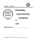
9 Refer to the NI Vision Acquisition Software Release Notes for specific installation off and unplug the protect yourself and the computer from electrical hazards, the computer must remain unplugged until the installation is the computer cover to expose the expansion a PCIe device into a PCI, PCI-X, AGP, or any non-PCIe slot can damage both the computer motherboard and the device. If you are unsure of the difference between connector types, do not install the device. Refer to the documentation provided by your computer manufacturer to determine the correct slot in which to install the NI a metal part of the computer to discharge any static electricity that might be on your clothes or body. Static electricity can damage the an unused x1 or larger PCIe slot, and remove the corresponding expansion slot cover on the back panel of the computer. Figure 1 shows the different types of expansion slots available on most NI 1427 is intended for a x1 PCIe slot.
10 The NI 1427 will fit into, and can be used in, a x4, x8, or x16 PCIe slot. National Instruments Corporation5 Getting Started with the NI PCIe-1427 Figure 1. PC Expansion your device from the antistatic package and gently rock the device into the slot. The connection may be tight, but do not force the device into that the bracket of the device aligns with the hole in the back panel rail of the computer the device mounting bracket to the back panel rail of the you will be using the NI Camera Link I/O Extension Board with the NI 1427, refer to the NI Camera Link I/O Extension Board User Guide for installation the computer the MDR 26-pin Camera Link cable to the Base configuration Camera Link-compatible camera. Refer to your camera manufacturer documentation for specific instructions about how to connect the cable to your Connect the Camera Link cable to the Camera Link connector on the NI 1427 front Plug in and power on the NI 1427 is now installed and the camera is 32-Bit Connector 2 PCI 64-Bit and/or PCI-X Connector3 PCIe x1 Connector 4 PCIe x16 Connector4213 Getting Started with the NI the NI 1427 After you have installed the NI 1427 and powered on the computer, the computer will recognize the device and assign resources to it.