Transcription of GFS 10 Fuel Sensor - Garmin International
1 GFS 10 fuel SensorGFS 10 fuel sensor installation Instructions 1 Instructions d installation du capteur de carburant GFS 10 5 Istruzioni di installazione del sensore del carburante GFS 10 9 Installationsanweisungen f r Kraftstoffsensor GFS 10 13 Instrucciones de instalaci n del Sensor de combustible GFS 10 17 Installationsvejledning til GFS 10 br ndstofsensor 21 Installeringsinstruksjoner for GFS 10 -drivstoffsensor 25 Installationsinstruktioner f r GFS 10 Br nslegivare 29 All rights reserved Except as expressly provided herein, no part of this manual may be reproduced, copied, transmitted, disseminated, downloaded or stored in any storage medium, for any purpose without the express prior written consent of Garmin Garmin hereby grants permission to download a single copy of this manual onto a hard drive or other electronic storage medium to be viewed and to print one copy of this manual or of any revision hereto.
2 Provided that such electronic or printed copy of this manual must contain the complete text of this copyright notice and provided further that any unauthorized commercial distribution of this manual or any revision hereto is strictly prohibited Information in this document is subject to change without notice Garmin reserves the right to change or improve its products and to make changes in the content without obligation to notify any person or organization of such changes or improvements Visit the Garmin Web site (www Garmin com) for current updates and supplemental information concerning the use and operation of this and other Garmin products Garmin and GFS are trademarks of Garmin Ltd or its subsidiaries, registered in the USA and other countries These trademarks may not be used without the express permission of Garmin GFS 10 fuel sensor installation Instructions 1 GFS 10 fuel sensor installation InstructionsTo obtain the best possible performance, install your GFS 10 fuel sensor according to the following instructions If you experience difficulty during the installation , contact Garmin Product Support.
3 Or seek the advice of a professional installer The GFS 10 will communicate with NMEA 2000- or Garmin CANet-compatible chartplotters and displays Refer to www Garmin com for a list of compatible devices WarnInGS The GFS 10 is designed for use with gasoline-engine fuel systems Do not use the GFS 10 with diesel-engine fuel systems. Do not use the GFS 10 with fuel that contains more than 10% ethanol such as E85 fuel . The GFS 10 is designed for use with single-line fuel systems Do not install the GFS 10 on engines with a return line to the fuel tank On pressurized fuel injected systems, the GFS 10 must be mounted on the low pressure side of the high-pressure fuel pump Engine-mounted fuel reservoirs may cause erratic flow readings The GFS 10 is not recommended for systems with large engine-mounted fuel reservoirs Gasoline is extremely flammable If possible, drain the fuel hose before you start, or shut any flow valves located near the tank Keep sparks and flame away from the work area Work in a well-ventilated area After installation , be sure to clean up any spilled fuel , and dispose of any spilled fuel in accordance with local laws Periodically check the GFS 10 installation for leaks.
4 And repair any leaks before using your boat See the Important Safety and Product Information guide in the product box for additional product warnings and other important information Product registrationHelp us better support you by completing our online registration at www Garmin com/registration/ For future reference, write the serial number assigned to your GFS 10 in the space provided It is located on a sticker on the back of the unit and on a sticker around the cable Serial number Contact GarminContact Garmin if you have any questions while using your GFS 10 In the USA contact Garmin Product Support by phone: (913) 397-8200 or (800) 800-1020, or go to www Garmin com/support/ In Europe, contact Garmin (Europe) Ltd at +44 (0) 870 8501241 (outside the UK) or 0808 2380000 (within the UK) Packing List and accessoriesBefore installing your unit, confirm that your package includes the following items If any parts are missing, contact your Garmin dealer immediately Standard Package GFS 10 fuel sensor unit 4 reusable stainless-steel hose clamps 3/8 in fuel filter (in-line) Mounting hardware CANet adapter NMEA 2000 T-connector installation instructionsOptional Accessories Additional NMEA 2000 network components CANet kit Replacement fuel filter Garmin recommends replacing the fuel filter at the start of each season or every 2,600 gal (10,000 L)
5 3/8 in hose compatible, 30-micron rated, E10 compatible Metal housing required for inboard applications West Marine part number 18-7857-1 or equivalentTools Needed Hose cutter or knife (to cut the fuel hose) Flathead and Phillips screwdrivers (to tighten the hose clamps and secure the unit) Drill and drill bits (to install the mounting hardware)2 GFS 10 fuel sensor installation InstructionsStep 1: Installing the GFS 10 in the fuel HoseEnsure that the fuel hose is drained, and use a hose cutter or a knife to cut the fuel hose where you want to install the GFS 10 Use the included hose clamps to secure the fuel hose to the GFS 10 Do not overtighten the clamps Inspect your fuel system and connections regularly Notes: Install the GFS 10 as far from the engine as practical Do not install the GFS 10 directly on the engine or where it could be subjected to excessive heat or vibration Do not install the GFS 10 between the engine and the priming bulb (if applicable) When placing the GFS 10 in the fuel hose, be sure the direction of flow, as indicated by the arrow, points toward the engine Install the GFS 10 so the fuel flows in an upward direction through the GFS 10 This will prevent errors caused by air bubbles Install the GFS 10 in a location above the maximum fuel level of the fuel tank Install the included fuel filter in the fuel hose between the fuel tank and the GFS 10 A sticker on the filter indicates the direction of fuel flow Always have a spare metal 3/8 in (9 5 mm)
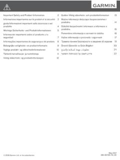
6 In-line fuel filter available If additional fuel hose is needed when installing the GFS 10 and fuel filter, use 3/8 in (9 5 mm) US Coast Guard type A1 fuel hose Have two 3/8 in (9 5 mm) in-line, fuel -line splice barbs available This allows you to remove the GFS 10 and the fuel filter, in case of an emergency, and maintain normal engine operation Be sure to clean up any spilled fuel Step 2: Mounting the GFS 10 and fuel FilterThe GFS 10, the in-line fuel filter, and the fuel hoses must be mounted to your boat A bracket for the GFS 10, cable ties with eyelets for the in-line fuel filter and hoses, and mounting screws are provided When mounting the GFS 10 to a solid structure on your boat, use the included bracket to secure the GFS 10 device, and use two included cable ties to secure the hose on either side of the GFS 10 When mounting the in-line fuel filter to a solid structure on your boat, use two cable ties around the fuel filter and two cable ties around the hose on either side of the fuel filter If you are unable to use the included bracket to secure the GFS 10 to a solid surface.
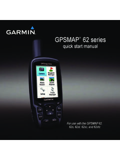
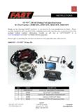
7 Use an included cable tie to secure the GFS 10 device to a bundle of cables or other hoses Use the included screws to mount the GFS 10 and the in-line fuel filter Drill a 1/8 in (3 2 mm) pilot hole for each screw If you are mounting the GFS 10 on fiberglass, use a countersink bit to drill a clearance counterbore through the top gelcoat layer (but no deeper) This will help to avoid cracking in the gelcoat layer when the screws are tightened Step 3: Connecting the GFS 10 to the Power Source and the fuel GaugeThe GFS 10 must be connected to the power source of the boat Optionally, the GFS 10 can be connected to the fuel gauge on your boat to read fuel -level data The bare-wire cable contains the power and ground wires, as well as the wires you connect to your fuel gauge Follow the wiring diagram to complete the connections +-red/WhiteBlack/WhiteGreyBrownOrangeFus eUnconnected(when using NMEA 2000)12 Vdc BatteryGroundIgnitionFuel Tank Level SensorTo NMEA 2000 Network or CANet BusWire AFuel gauge connection optionalIMPORTANT.
8 If you use a fuse block on your boat, cut the fuse holder from the power wire Use a 25 A fuse in the fuse block Install the fuse holder as close to the battery as possible If an extended run of wire is needed, add 24 AWG wire between the fuse holder and the GFS 10, not between the fuse holder and the battery DO NOT install the fuse holder near the gas tank If you do not connect the GFS 10 to a fuel gauge or level- Sensor on a fuel tank, connect the brown wire to ground, and leave the grey wire unconnected EngineFuel tankGFS 10 fuel filterTo power and data connectionsCable tie ( 6)BracketGFS 10 fuel sensor installation Instructions 3 Notes: Consult the owner s manual provided by your boat manufacturer to determine the ground, ignition, and level- Sensor connections on your fuel gauge Often, the ignition connector is labeled I or + , and the level- Sensor connector is labeled S If you do not have a fuel gauge , but you do have a fuel tank with a level Sensor , connect the brown wire to the + terminal of the level Sensor at the tank DO NOT install the fuse holder near the tank extend the brown wire to the tank with 24 AWG wire Complete this connection before completing any other wiring connections to reduce the risk of a spark near the fuel tank Leave the grey wire unconnected If you are using NMEA 2000, be sure to leave the orange wire unconnected Multiple GFS 10 DevicesIf your boat has more than one engine or fuel tank.
9 You will need multiple GFS 10 devices Each GFS 10 can function as one flow Sensor and one level Sensor You need one GFS 10 flow Sensor for each engine, and one GFS 10 level Sensor for each fuel gauge or for each fuel tank that has a level Sensor Depending on your boat, you may use only the flow-sensing capabilities of additional GFS 10 devices Flow SensingMultiple enginesOne GFS 10 per engine up to four engines Multiple fuel tanks for one engineOne GFS 10 per engine install after the tank switchLevel SensingMultiple tanks with one fuel gauge and a manual switchOne GFS 10 wired to the fuel gaugeMultiple fuel tanks with multiple gaugesOne GFS 10 per tank wired to each gauge up to two tanksMultiple fuel tanks with no fuel gaugeOne GFS 10 per tank wired to the level Sensor (if available) up to two tanks nOTE: When using multiple GFS 10 units on multiple engines, it is normal to read different fuel flow rates on each GFS 10 unit Similar engines do not always consume fuel at the same rate Step 4: Connecting the GFS 10 to Your ChartplotterThe GFS 10 transmits data to your chartplotter or Marine Instrument using either NMEA 2000 or Garmin CANet Connecting the GFS 10 through nMEa 2000 The GFS 10 is packaged with a NMEA 2000 T-connector The GFS 10 has a built-in NMEA 2000 drop cable Use these two components to connect the GFS 10 to your existing NMEA 2000 network If you do not have an existing NMEA 2000 network, you will need to install a NMEA 2000 network on your boat For more information on NMEA 2000, visit www Garmin com To connect the GFS 10 to your existing NMEA 2000 network:1.
10 Determine an appropriate location to connect the GFS 10 to your existing NMEA 2000 backbone 2. Disconnect one side of a NMEA 2000 T-connector from the backbone nearest to the location where you want to connect the GFS 10 If you need to extend the NMEA 2000 backbone, connect an appropriate NMEA 2000 backbone extension cable (not included) to the T-connector you disconnected 3. Connect the included T-connector for the GFS 10 to the NMEA 2000 backbone 4. Route the built-in drop cable on the GFS 10 to the bottom of the T-connector you added to your NMEA 2000 network If the built-in drop cable is not long enough, you can add a drop cable extension up to 14 ft (4 m) If more cable is needed, add an extension to your NMEA 2000 backbone, based on the NMEA 2000 guidelines Connecting the GFS 10 through Garmin CanetThe GFS 10 is packaged with a Garmin CANet adapter that you can use to connect the GFS 10 to your existing Garmin CANet bus If you do not have an existing CANet bus, you will need to install a CANet bus on yo