Transcription of Glenn Elmore, N6GN John Watrous, K6ZPB
1 Glenn Elmore, N6GN John Watrous, K6 ZPB. 446 Halter Ct, Santa Rosa, CA 95401; PO Box 495, Graton, CA 95444; A Surface Wave Transmission Line This article is the first in a series of QEX articles that involve surface wave transmission line theory and applications for use by radio amateurs. The second article describes a balloon supported flying antenna.. The third article describes a very wide band antenna. Many we've shown this to have a first and have difficulty understanding that this voltage is highest there. As a result of that response of something like How can a sig- SWTL isn't one, it is perhaps useful to first discontinuity a free wave is radiated into the nal hooked to a long wire not radiate?
2 This consider the familiar dipole. A dipole can surrounding space while at the same time a particular type of transmission line has not make a good antenna, particularly when it reflected wave returns toward the center. been previously described in the Amateur is an odd number of half wavelengths long. A dipole simultaneously exhibits prop- Radio literature, but it may be mistaken for You may have operated a 40 meter dipole on erties characteristic of a radiator, a trans- one that has. Surface wave propagation has both 40 and on its 3rd harmonic at 15 meters. mission line and a A monopole been known for a very long time.
3 In fact, in A dipole can be fed from the middle and element fed from the end does this as well. the early days of radio, prior to 1900, theo- exhibits resonance at the fundamental, 3rd, If we put a load at the far end of an ele- retical work was done by Sommerfeld to ment that is able to couple to the signal explain beyond the horizon propagation. (wave) and prevent both reflection and Then in the 1950s, Georg Goubau intro- radiation, then the resonance disap- duced a new surface wave transmission pears and signal energy goes into that line (SWTL) that required only a single load. If you've ever grabbed the end That line, known since as of a driven element of a VHF or UHF.
4 G-line, required dielectric (insulation) Yagi with your hand while watching around the wire or else special featur- an SWR meter you have witnessed this ing of the conductor to slow the relative effect. The structure operated less like velocity of propagation in order to keep an antenna. Depending upon whether the signal from leaving the wire con- you were transmitting or receiving, sig- ductor. Reference books, including The nal power to or from a distant locations ARRL VHF Manual, provided informa- was reduced, resonance was suppressed tion from Goubau's work and a 1974 and some of any transmitted energy QST article by George Hatherell, K6LK, was absorbed in your hand.
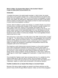
5 Under these further described the use of this unusual conditions, the driven element became mode for amateur radio , 3 Completed 144 MHz launcher mounted on a holder.. more of a transmission line and less of The SWTL being described here does The of no. 24 SWTL conductor extends from the center the horn and can be seen as a faint line in a radiator. Energy put into the element not use the same mode as described for this photograph. traveled as a wave along the conductor G-Line. Unlike G-line, no insulation or and was absorbed into a load at the end. conditioning around the conductor is neces- 5 and higher odd harmonics.
6 In a sense, th 4 With appropriate coupling and loading, this sary. In fact, a bare conductor can actually a resonant dipole, knows how long it is behavior can occur at all frequencies, not just work better than one with insulation, at least that is, by connecting only at the center, at frequencies where the unloaded element while the surface is bright and shiny. Also, responses due to total length can be seen. A happens to be resonant. With proper con- there is no slowing of the propagating wave. dipole's response depends upon the length nections, called launchers at each end of a The wave may travel more than 50% faster and on something happening at the element conductor, a simple transmission line that than signals in common coax and has been ends.
7 Exhibits very low attenuation along with measured to have a relative propagation very wide bandwidth operation can result. A monopole fed against a ground can velocity of unity it travels right at the The plot in Figure 1 compares the measured be thought of rather like a dipole. Fed from speed of light. attenuation of 100 feet of a SWTL made one end, the signal (wave) travels to the far For those who are familiar with antennas from no. 24 AWG copper wire conductor end of an element and is reflected back from the discontinuity there. Since the conductor with the attenuation of LMR400 coax. Not 1 Notes appear on page 00 ceases at the end, real current is zero and only is this SWTL simpler, less expensive QEX May/June 2012 3.
8 Table 1 Materials and Sources for Building the Launcher 1. Pacon Metallic-Colored Four-Ply Poster Board: B002 XJHGDK/f=sr_1_3?ie=UTF8&s=office-cts&qid =1309381399&sr=8-3. 2. SMA connector: 3. inch brass shim stock: 4. No. 24 Magnet wire: 5. Metal tape: 6. K&S brass tubing stock in various sizes: Available from many local hobby and hardware stores. 7. Styrofoam insulation, 2 inches thick: Available at most home building supply stores. and lighter than coax, but above a lower With the overlapping tab lined up along the than the required length to allow for overlap at frequency limit which is determined by the entire inside length, temporarily tape the cone each end.
9 Carefully position these, both as to launcher design, it can also exhibit lower loss together on the inside with transparent tape length and straightness, and tack solder them than even this excellent coax. or masking tape. Then go back and tape the together. Once you have the entire tapered cen- While the preceding discussion may help entire outer seam with metal foil tape. It may ter conductor assembled and are pleased with describe the SWTL for those familiar with help to have two people for this operation. the lengths and alignment, you can go back and antennas, the question How can a trans- Similarly, with the brass shim pattern, solder each joint completely.
10 Finally, sand or mission line as simple as this not have been once cut out, overlap the edges carefully and file away any excess solder so that you finish discovered and used before? may still occur. tack solder it in a few places to hold it in place with a smooth step-tapered center conductor. For those who prefer to examine the SWTL before going back and completely soldering Cut a Styrofoam stiffener from 2 inch stock. from the point of view of transmission line the seam. This is available from home supply stores for rather than antenna theory, more detail on When you are finished building these use as thermal insulation.