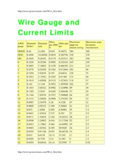
Transcription of GM D1063S Load Cell Strain Gauge Bridge Isol …
1 Procon Engineering (A Division of National Oilwell Varco UK Ltd) Model D1063S load Cell/ Strain Gauge Bridge Galvanic Isolating Repeater Up to four 350 load cells in parallel or twelve 1000 in parallel EMC compatibility to EN61000-6-2, EN61000-6-4 high accuracy ATEX approved high reliability, SMD components simplified installation using standard DIN rail and plug-in terminal blocks The D1063S acts as transparent and very accurate galvanic isolated interface installed between a weighing indicator/system in the Safe Area and a load cell (or group of load cells ) in a Hazardous Location.
2 The output to the indicator/system is a transparent reflection of a single load cell equivalent to the one/s in the field. The unit located in Hazardous Location repeats with isolation the mV signal output to drive the load in the Safe Area dependent upon the host system reference voltage. Up to four 350 Ohm load cells , or six 400 Ohm load cells , or twelve Ohm load cells can be connected in parallel. In addition a field-wiring fault LED indicates any lead break in the Hazardous Location side. Approved for Div. 2 installation. Hazardous area: Up to four 6 wire paralleled load cells 350 Ohm, 5 V, 80 mA total capacity.
3 Safe area: mV corresponding to Input Bridge voltage. Accuracy, after system calibration: %. Function: 1 channel input from Strain Gauge signals, provides 3 port isolation (input/output/supply) and repeats, as a transparent unit, Bridge signal output. A Division of National Oilwell UK Ltd Issue 2. November 2014technical specification sheet Model D1063S load Cell/ Strain Gauge Bridge Isolating Repeater SPECIFICATION Supply: 24 Vdc nom (20 to 30 Vdc) reverse polarity protected, ripple within voltage limits 5 Vpp. Current consumption @ 24 V: 80 mA with four 350 load cells connected, typical.
4 Power dissipation: W with 24 V supply and four 350 load cells connected typical. Max. power consumption: At 30 V supply voltage and short circuit input, W. Isolation (Test Voltage): In/Out KV; In/Supply KV; Out/Supply 500 V. Input: Up to four 350 load cells in parallel or up to six 450 load cells in parallel or up to twelve 1000 load cells in parallel Bridge supply voltage: V nominal. Bridge output signal: 2 mV/V. Input range: 9 mV nominal span, 11 mV over range. Line resistance compensation: 10 . Burnout: LED indication for field wire breakage.
5 Output: 10 mV nominal span, 12 mV over range (5 V reference voltage), 20 mV nominal span, 24 mV over range (10 V reference voltage). Output impedance: 350 typical. Host reference voltage: 10 V typical, 11 V maximum. Internal reference voltage: 10 V typical, DIP switch settable. Internal impedance: 350 typical, DIP switch settable. Transfer characteristic: Linear based on mV input. Response time: 100 ms (10 to 90 % step change). Performance: Ref. Conditions 24 V supply, 23 1 C ambient temperature. Calibration accuracy after system calibration: % of full scale of input range.
6 Linearity accuracy: % of full scale of input range. Supply voltage influence: % of full scale for a min to max supply change. Temperature influence: % of full scale of input range for a 1 C change. Compatibility: CE mark compliant, conforms to 94/9/EC Atex Directive and to 2004/108/CE EMC Directive. Environmental conditions: Operating: Temperature limits -20 to + 60 C, relative humidity max 90 % non condensing, up to 35 C. Storage: Temperature limits 45 to + 80 C. Mounting: T35 DIN Rail according to EN50022. Weight: 165 g. Connection: by polarized plug-in disconnect screw terminal blocks to accommodate terminations up to mm2.
7 Location: Safe Area/Non Hazardous Locations or Zone 2, Group IIC T4, Class I, Division 2, Groups A, B, C, D Temperature Code T4 and Class I, Zone 2, Group IIC, IIB, IIA T4 installation. Protection class: IP 20. Dimensions: Width mm, Depth 99 mm, Height mm. Function Diagram: Procon Engineering s policy is one of continuous product enhancement. We therefore reserve the right to incorporate technical modifications without prior notification. E & O E. Procon Engineering Vestry Estate Sevenoaks Kent, UK TN14 5EL tel: +44 (0)1732 781300 fax: +44 (0)1732 781311 web site: Up to 4 load cells 350 in parallel Up to 6 load cells 450 in parallel Up to 12 load cells 1000 in parallel