Transcription of GPIO Interrupts (EXTI) on STM32 Microcontrollers using HAL
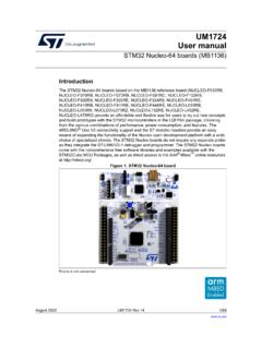
1 STM32 Tutorial nucleo F103RB GPIO Pins created on simon burkhardt page 1 /5 GPIO Interrupts (EXTI) on STM32 Microcontrollers using HAL with FreeRTOS enabled The STM32 microcontroller family offers multiple GPIO interrupt pins. The STM32 CubeMX Software comes in handy when configuring the parameters of these pins. However, the actual usage of This tutorial uses the following equipment: - nucleo -F072RB board - Keil uVision 5 with the necessary packages for nucleo boards installed - STLink USB Driver - STM32 CubeMX - External LED on PC8 (to demonstrate that the endless loop is not affected) STM32 CubeMX Generating the config.
2 Files from STM32 CubeMX. 1. Open STM32 CubeMX and open a new project. 2. Select the nucleo -F072RB from the Borards tab 3. Enable FreeRTOS 4. Set the RCC (HSE & LSE) to Crystal/Ceramic Resonator 5. Enable the USART2 port in Asynchronous mode 6. (optional) set any GPIO pin as output (and connect an LED to it, here PC8 is used) 7. Set PC13 as GPIO_EXTI13 (this is the blue user button on the nucleo ) STM32 Tutorial nucleo F103RB GPIO Pins created on simon burkhardt page 2 /5 8. Click the configuration tab and click on the GPIO button 9.
3 Here you can set the interrupt parameters for EXTI13 I set the GPIO mode to detect falling edges (since the user button has a pull-up resistor) Hit Apply and Ok to save the changes. 10. Next, click the NVIC button 11. Enable EXTI lines 4 15 (since we use EXTI13) 12. The priority is 3 by default, this is because we are using FreeRTOS 13. Go to Project > Generate code 14. Enter a project name and select MDK-ARM V5 15. Generate the code and open the project in Keil uVision STM32 Tutorial nucleo F103RB GPIO Pins created on simon burkhardt page 3 /5 The code generator should output the desired code as usual.
4 Note, that the EXTI initialisation takes part within the GPIO init function call. On line 206, the GPIO mode is set to detect Interrupts on falling edges. This initialisation is found at the end of the GPIO init. Set a default task in an endless loop So we can test that the interrupt is working. Type the following into the endless loop of the default task. This simply shows, that the endless loop keeps running when we trigger an EXTI interrupt. Do something on an interrupt event Open the file That is where the magic happens.
5 Somewhere on line 73 should be a function called EXTI4_15_IRQH andler. Each time an EXTI interrupt is triggered, this function gets called. The statement between the two user code segments simply clears the interrupt flag of the EXTI channels. Now to execute something on an EXTI interrupt event, you could simply add your code between the user code blocks. This code is then executed with every EXTI event on any enabled EXTI channel. 204 205 206 207 208 209 /*Configure GPIO pin : PC13 */ = GPIO_PIN_13; = GPIO_MODE_IT_FALLING; = GPIO_NOPULL; HAL_GPIO_Init(GPIOC, &GPIO_InitStruct); 224 225 226 227 /* EXTI interrupt init*/ HAL_NVIC_SetPriority(EXTI4_15_IRQn, 3, 0); HAL_NVIC_EnableIRQ(EXTI4_15_IRQn); 238 239 240 241 242 243 244 245 246 /* USER CODE BEGIN 5 */ /* Infinite loop */ for(;;) { GPIOC -> ODR ^= GPIO_PIN_8; // toggle the LED on & off osDelay(500).}
6 } /* USER CODE END 5 */ STM32 Tutorial nucleo F103RB GPIO Pins created on simon burkhardt page 4 /5 Filter EXTI interrupt events But you might want to do different things, when different interrupt pins are triggered. You can filter the interrupt event with a simple if-statement (see on line 76). It is important to place this if statement before clearing the interrupt flags (line 80). The instructions within the if-statement is only executed when an EXTI interrupt on EXTI channel 13 occurs.
7 Keep the following makro in mind when filtering EXTI interrups: It takes the EXTI channel as an argument, where x is any numer from 0 to 15. It returns true, when the interrupt flag for the given channel is set. Test the program If you compile and upload the code, the LED connected to PC8 should blink independently of the user button. With every press of the user button, the LD2 LED on the nucleo board should toggle. 73 74 75 76 77 78 79 80 81 82 83 84 85 void EXTI4_15_IRQH andler(void) { /* USER CODE BEGIN EXTI4_15_IRQn 0 */ if(__HAL_GPIO_EXTI_GET_FLAG(GPIO_PIN_13) ){ LD2_GPIO_Port -> ODR ^= LD2_Pin; // toggle LD2 LED } /* USER CODE END EXTI4_15_IRQn 0 */ HAL_GPIO_EXTI_IRQH andler(GPIO_PIN_13).}
8 /* USER CODE BEGIN EXTI4_15_IRQn 1 */ /* USER CODE END EXTI4_15_IRQn 1 */ } 1 __HAL_GPIO_EXTI_GET_FLAG(GPIO_PIN_x) STM32 Tutorial nucleo F103RB GPIO Pins created on simon burkhardt page 5 /5 Document Created by Simon Burkhardt This tutorial is very basic and might not show the best way to use the STM32 environment. It still might help you get into the whole HAL philosophy of STM if you are coming from another platform. This document is free of copyright under the Creative Commons Zero attribution.
9 Simon Burkhardt electronical engineering History: tested the code, created this document added contact info and cc0 notice