Transcription of GPS Guidelines for RTN/RTK GNSS Field work in Connecticut
1 GPS Guidelines for RTN/RTK gnss Field work in Connecticut October 2013 DRAFT Version Version 1st CT_Draft October 2013 Page 1 Contents Table of Acronyms .. 2 1. Introduction .. 3 2. RTK/RTN Overview & Description .. 4 RTK vs. RTN .. 5 RTN Issues .. 6 RTK Issues .. 6 Site Conditions .. 6 Base Station Coordinates .. 7 3. Project Planning .. 8 Theoretical Suitability .. 8 Practical Considerations .. 9 Project Site .. 9 Communication .. 9 RTN Base Stations .. 10 RTK Base Stations .. 10 RTK/RTN Rovers .. 10 Project Configuration .. 11 4. Survey Procedures .. 11 Equipment Calibration & Setup .. 11 Rover Receiver 11 Rover 13 Rover Initialization & Survey Environment .. 14 RTK Initialization .. 14 Environmental Error Sources .. 15 Field Survey .. 16 Communications .. 16 Rover QC Indicators .. 16 Quality Control .. 17 RTK Base Station Quality Control.
2 18 Post Processing .. 18 Horizontal Calibration .. 18 Vertical Calibration .. 19 5. Summary and Conclusions .. 19 REFERENCES .. 21 Appendix A Summary of North America Datum in Connecticut .. 22 Appendix B Field Checklist .. 23 Appendix C Questions To Ask Your RTN Service 26 Appendix D RTN Coverage in Connecticut .. 27 Version 1st CT_Draft October 2013 Page 2 Table of Acronyms ARP: Antenna Reference Point ACORN: Advanced Continuous Operating Reference Network GDOP: Geometric Dilution of Precision VDOP: Vertical Dilution of Precision HDOP: Horizontal Dilution of Precision PDOP: Position Dilution of Precision GLONASS: Globalnaya Navigatsionnaya Sputnikovaya Sistema or Global Navigation Satellite System gnss : Global Navigation Satellite System GPS: Global Positioning System HI: Height of Instrument. In RTK this refers to the distance from the physical point to the Antenna Reference Point (ARP) NAD83: North American Datum 1983 RTK: Real Time Kinematic RTN: Real Time Network Version 1st CT_Draft October 2013 Page 3 1.
3 Introduction The Connecticut Department of Transportation has partnered with the University of Connecticut to provide a Real Time GPS Network for the state of Connecticut and neighboring states. There is nine GPS base station strategically located across the state to maximize the cover. This network will be available to anyone who has a professional need for corrected GPS coordinates. The user must be at a proficient level with the technology. The CTDOT or UCONN will not provide any technical support if needed. There will be a Network administrator located at UCONN that will receive the request for user name and password to the network. This administrator will be responsible for the network integrity but will not provide individual support to the user. Due to the infancy of the GPS network the CTDOT and UCONN will be providing the user name and password free for a year to pilot the volume of user traffic to the network.
4 The website to request user account is Click the link and fill out request and click submit and you will receive an email with your ACORN user account information. The goal of this document is to provide best practice Guidelines for achieving centimeter level RTK/RTN surveys and construction inspection. This document is being created to decide the GPS solution to be used per project. This document contains recommendations for all aspects of RTK/RTN use, including a comparison of RTK and RTN methods. This document serves as a reference, as well as a reminder of what is important. Appendix B includes a Field checklist that can be used as a quick reference when doing RTK/RTN measurement and Appendix C lists important questions that any RTN user should ask their provider as part of their project planning. The first method being discussed in this document is Real Time Kinematic.
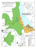
5 (RTK) This method uses Global Navigation Satellite Systems ( gnss ) and is now a common method used for both cadastral and engineering surveys in Connecticut . In recent years the number and extent of public and private Real Time Networks (RTN) along the east coast has been rapidly increasing. RTN use is becoming more popular where available, but RTK is still the only option available in some parts of Connecticut . To see the current RTN coverage in Connecticut refer to the coverage map in Appendix D (ACORN Scatter map). Both RTK and RTN positioning can achieve relative centimeter (cm) precision when following a set of best practices. There are several important factors that need to be accounted for when doing RTK/RTN activity. Many of these are common to other types of gnss use and include: equipment calibration, atmospheric errors, multipath, satellite geometry, reference system integration, redundancy, and validation.
6 There are also some recommendations in this document which are unique to RTK/RTN and include things such as rover setup, communication problems, time windowing, and initialization. Version 1st CT_Draft October 2013 Page 4 Throughout this document the following terms are used: Users: Anyone performing either RTK or RTN surveys and or Field layout. gnss : Global Navigation Satellite System and will be used to describe GPS, or GPS+GLONASS (as well as other systems ( Galileo) as they come online). Users should generally apply the same practices whether using GPS only or gnss . The main advantage of gnss is the increased number of satellites which improves the geometry (especially when working in urban canyons or other partially blocked areas). RTK: Single base Real Time Kinematic gnss surveys. RTN: Real Time Network gnss surveys. Also used to describe the network of Real Time base stations.
7 RTN is also known as Network RTK (NRTK) 2. RTK/RTN Overview & Description RTK positioning is a relative technique which measures the position of two gnss antennas comparable to each other in real-time. One antenna is setup on a static point with fixed coordinates and is known as the base station. The RTK base station transmits its raw observations to the rover(s) in real-time and the rover uses both the rover and base observations to compute its position relative to the base (see figure 2-1). Figure 2-1 Typical RTK Setup. After a short initialization time (<1min) the rover can continuously determine a precise 3D vector relative to the base station. This type of measurement requires a reliable communications link between the base and rover as the rover needs continuous observations from the base. RTK has proven to be a reliable and efficient means for determining precise relative baselines.
8 However, this method is limited to baselines of approximately 6 miles due to the effect that distance related errors (atmosphere, and satellite orbits) have on the initialization, and solution precision. The precision of RTK decreases as the baseline length increases. Real Time Network (RTN) surveying has been developed to overcome this base-to-rover range limitation. The RTN concept is that a group of base stations will collect gnss observations and send them in real-time to a central processing system (ACORN). The central processor will then combine the observations from all (or subset) of the base stations and compute a network solution. From this network solution the observation errors and their corrections are computed and broadcast to rovers working within the bounds of the RTN. There are different RTN approaches in use including the virtual reference station (VRS) and master auxiliary concept (MAC).
9 For more information on the different RTN approaches the reader is encouraged to check their Version 1st CT_Draft October 2013 Page 5 manufacturer s documentation, or to check some of the references in this document. Figure 2-1 Typical RTN Schema RTK vs. RTN This section describes the differences between working with RTK and RTN. Despite their differences, both methods can continue to provide relative 3D accuracies to within feet horizontally or to feet vertically. Base Station Working with RTK requires the purchase, maintenance, monitoring, and setup of a base station(s). This can be both time consuming and costly, as well as technically challenging for novice users. For some expert users however, working with their own base station(s) does allow for more control over the technical aspects of the base station setup and correction delivery. Working with RTN allows the users to leave the burden of setting up, maintaining, and monitoring the base station(s) to the network operator (UCONN).
10 The RTN user is required only to purchase a network subscription for access to the base stations and a cellular data plan. Communications RTN operators normally use a cellular provider. This means that corrections can only be received where cellular coverage exists. Single base RTK surveys normally use UHF, VHF or broad spectrum radios. This removes the reliance on cellular coverage but limits the baseline length to Version 1st CT_Draft October 2013 Page 6 the range of the radio link making RTK surveys over large areas challenging. Solution Quality The precision of single base RTK decreases as the baseline length increases. To achieve the accuracy with RTK it might be necessary to set/up multiple base stations or to use a repeater or booster radio with relatively short baselines, both of which will increase the cost and reduce the efficiency of the survey. RTN has been developed to overcome this base-to-rover range limitation and will give comparable result from anywhere within range the network.