Transcription of GPS10R/RB - 10 MHz, GPS Disciplined, Rubidium Frequency ...
1 GPS10R/RB Brochure. Precision Test Systems LTD 2000-2006 GPS10R/RB - 10 MHz, GPS disciplined , Rubidium Frequency Standards Key Features Completely self-contained units. No extra computer needed. Full information available via LCD. Rubidium Oscillator locked to GPS satellite signal. Accuracy to parts in 10-13 (Stratum 1 performance) Free run mode. Rubidium still gives an accurate output without a GPS satellite signal (Stratum 1, 72 hr) Two 1 pps time outputs. Typical error < 20 ns compared to UTC. Jitter < 300 ps Ultra Low Phase Noise, -148 dBc/Hz at 1 kHz offset Multiple 10 MHz Frequency Outputs plus other outputs RS232 interface. Full control and interrogation of the GPS10R/RB via RS232 19 2U high rack mountable case (GPS10RB) or bench mount unit (GPS10R) Very Low Microphonics Optional DDS Outputs.
2 Generate any Frequency from 0 to 1640 MHz in 1 or 10 Hz steps Optional DDS with Sine and Cosine outputs Optional single Frequency output. Single Frequency is fixed and can be anywhere from 0 to 10 GHz Optional alarm relay outputs. Dual changeover relay is operated in an alarm condition Optional antenna amplifier. Place GPS antenna up to 350 m (1150 feet) away from GPS10R/RB Optional time code outputs (BCD, IRIG-B, IRIG-E and ESE-TC90) Optional redundancy. Operate two units in a redundancy set-up for added security with automatic switchover. Five 10 MHz outputs as standard. More outputs can be added if required. GPS10R/RB Brochure. Precision Test Systems LTD 2000-2006 Optional Slave Clock Display. Display provides 25 mm high digits of time or date Optional Windows Software. Allows GPS10R/RB to be monitored from a remote location Optional GSM Interface.
3 GPS10R/RB can send a SMS to ten GSM phones in the event of an alarm Optional additional outputs. Up to 100 extra sinewave outputs can be added (requires separate box) Optional 5 MHz outputs instead of 10 MHz. A 10 MHz output is still available Optional high quality distribution amplifier giving increased isolation and phase stability Optional Ethernet interface. Enables the GPS10R/RB to communicate over the internet Custom built options available upon request High quality design General Description The GPS10R/RB are 10 MHz, GPS disciplined , Rubidium Frequency standards. They combine the short-term stability of an atomic Rubidium oscillator with the long-term stability and traceability of the Global Positioning Service (GPS) set of satellites. The GPS10R/RB achieves short and long-term Frequency accuracy of parts in 10-13.
4 Thus the GPS10R/RB exceeds the requirements of a Stratum 1 level Frequency standard. Options for the GPS10R/RB include an antenna amplifier enabling the antenna to be placed up to 350 meters from the GPS10R/RB , various fixed high Frequency outputs, alarm relay outputs, redundancy, battery backup supply, time code outputs and a variable Frequency output. Rubidium for the price of an OXCO Oscillator The GPS10R/RB incorporate an atomic Rubidium oscillator as the main Frequency reference, but costs the same as some competitive units that use less accurate crystal oscillators. The Rubidium used in the GPS10R/RB is 30 times more stable than any OXCO available. This means the GPS10R/RB achieves a Frequency stability of typically 7 x 10-13 in 1000 sec. Frequency Standards that use a crystal oscillator as the main reference can only achieve this stability when measurements are averaged over one week or one month.
5 This means the GPS10R/RB can be used as a Frequency reference for Frequency counters etc and measurements can be made in seconds, not days or weeks as is the case for crystal oscillator based units. Accurate Timing Outputs There are two 1 pps (pulse per second) outputs that are derived from the GPS receiver or the Rubidium oscillator. The 1 pps signal from the GPS receiver is aligned to UTC with less than 20 ns error. The 1 pps from the Rubidium is also aligned to UTC but has the advantage of less than 300 ps jitter (typically < 150 ps). Most other Frequency standards quote 50-100 ns jitter. Very Low Phase Noise The GPS10R/RB are one of the lowest phase noise Frequency standards available, at any price! Phase noise is often overlooked, but is one of the most important specifications of a Frequency standard.
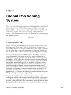
6 Many of today's high performance signal generators, for example, have very low phase noise outputs. These signal generators have their own internal, low phase noise, crystal oscillator. However, if this type of instrument is used with an external Frequency source, it is essential that the external Frequency source has an equally low phase noise output as the internal oscillator. Otherwise the signal generators phase noise will be impaired. Of course it's not only signal generators that could suffer, but also any other type of instrument that relies on a low phase noise Frequency source, to operate correctly. GPS10R/RB Brochure. Precision Test Systems LTD 2000-2006 GPS10RB Phase Noise Comparison-160-150-140-130-120-110-100-9 0-80-70110 100 1k 10k 100kFrequency Offset (Hz)Phase Noise (dBm/Hz)GPS10 RBCompetitor ACompetitor BCompetitor C The graph to the left shows the GPS10R/RB phase noise (red trace) compared with three competitors (Pink, Yellow, Blue traces).
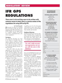
7 As can be seen the GPS10R/RB has lower phase noise than its competitors. Competitor s specifications drawn from internet publications. GPS10R/RB phase noise independently measured (smoothed display). Keyboard Control and LCD Display A 16-way keyboard is used to interface to three microprocessors that control the GPS10R/RB . The LCD display's over 50 different menus. These menus show all the relevant information including time, position (longitude, latitude, height), number of satellite tracked, health of each satellite and the status of the Rubidium oscillator. Allan Variance Plot of the GPS10R/RB and the GPS signal The diagram below shows the Allan variance of a typical GPS signal (pink), the Allan variance of the GPS10R/RB 's Rubidium oscillator when free running (not locked to the GPS signal) (yellow) and the actual output of the GPS10R/RB when locked to the GPS signal (blue).
8 As can be seen, the GPS10R/RB combines the short-term stability of the Rubidium oscillator with the long-term stability of the GPS signal to achieve short and long term stability of its Frequency output signal. Multiple Frequency Outputs The GPS10R/RB has many different output options. These outputs are: Buffered 10 MHz sinewave outputs. Each output is fully isolated from each other. The amplitude of each output can be individually adjusted from 0 dBm to +13 dBm. Harmonic distortion of these outputs is better than -65 dBc. Five outputs as standard. Option 12 adds a further five, making ten in total. Square wave output that can drive TTL levels into a 50 load impedance. The Frequency of the square wave can be set to 10, 5, 2, 1, MHz and 1 pps via the front panel keyboard. One output as standard and two available with option 12.
9 Dual one pulse per second outputs. These 1 pps outputs are either derived from the GPS receiver, or from the Rubidium receiver. The leading edge of the GPS 1 pps signal is aligned to UTC time 20 ns. The Rb 1 pps output signal has very low jitter of < 300 ps. These outputs can drive TTL levels into a 50 load impedance. A slave 10 MHz output is available to connect more distribution amplifiers, such as the PTS50 or DA101010, to the GPS10R/RB . Thus it is possible to get multiple 10 MHz outputs that can be used to provide 10 MHz reference signals to an entire building or workshop, for example. GPS10R/RB Brochure. Precision Test Systems LTD 2000-2006 Optional high Frequency outputs can be specified at the time of ordering. These fixed high Frequency outputs can be as high at 10 GHz (higher frequencies available upon special request) and are phase locked to the main Frequency reference.
10 Note: this option only generates one fixed Frequency . Optional DDS Output enables the GPS10R/RB to produce a sinewave or squarewave output that is locked to the GPS10R/RB . The Frequency range of this output is 1 Hz to 80 MHz (1 Hz steps) or 10 Hz to 1640 MHz (10 Hz steps). This option can be used to generate the popular 2048 kHz and 13 MHz frequencies as well as any Frequency in the range 1 Hz to 80 MHz or 10 Hz to 1640 MHz. Optional Time Code Output. This option generates the industry standard IRIG-B, IRIG-E and ESE-TC90) time code formats. Also a 48 bit BCD time code can be generated with option 16. Free Run Mode. Ideal for portable applications The GPS10R/RB is normally operated with the Rubidium oscillator's 10 MHz output, locked to the GPS satellite system.