Transcription of GREENHECK
1 Part # 457046. Installation, Operation and Maintenance Instructions for MAKE UP AIR UNITS. with Electric Heaters and Steam, Water and DX coils WARNING: Improper installation, adjustment, alteration, service or maintenance can cause property damage, injury or death. Read the installation, operating and, maintenance instructions thoroughly before installing or servicing this equipment. This manual is the property of the owner, and is required for future maintenance. Please leave it with the owner when you complete the job. GREENHECK . BOX 410 SCHOFIELD, WISCONSIN 54476-0410. PH. 715-359-6171. September 1997. Table of Contents Receiving and Handling .. Pg. 2. 2. Electric Heater .. Pgs. 3-5. Steam Pg. 6 -7. DX Pg. 7. Water Pg. 8. Coil 8. Receiving and Handling Upon receiving the equipment, check for both obvious and hidden damage.
2 If damage is found, record all necessary information on the bill of lading and file a claim with the final carrier. Check also to be sure all parts of the shipment, including accessories, are accounted for. Storage When a fan is to be stored prior to installation (or for any long period of time) it must be protected from dirt and moisture. Covering the unit will aid in keeping it clean and dry. Plastic or vinyl sheeting should not be used, since they promote condensation. Improper storage which results in damage to the unit will void the warranty. The wheel and motor should be rotated periodically if the storage period is lengthy. Once every three months is recommended. Unit Installation This unit should be installed according to the GFC IOM: # 456856 for TSU's. Warranty GREENHECK Fan Corporation warrants this equipment to be free from defects in material and workmanship for a period of one year from the purchase date.
3 Any units or parts which prove to be defective during the warranty period will be repaired or replaced at our option. The motor is warranted by the motor manufacturer for a period of one year. Should the motor prove defective during this period, it should be returned to an authorized motor service station. GREENHECK Fan Corporation will not be responsible for any installation or removal costs. Due to continuing research, GREENHECK reserves the right to change specifications without notice. 2. Electric Heater Option WARNING: Electrical Shock Hazard! Disconnect all Power sources before doing any work on the unit. General: The requirements and practices described below are based on the National Electric Code and The Space Heating Standard of the Underwriters Laboratories Inc. (UL).
4 Although UL requirements are uniform throughout the country, local electrical codes may deviate from the National Electrical Code; therefore, local inspection authorities should be consulted regarding local requirements. Electrical Wiring Instructions: 1. Use the wiring diagram supplied with the heater as a guide in correlating field wiring with the heater internal wiring. 2. All field wiring to the heater must meet the requirements of the National Electric Code (NEC) and any other applicable local or state codes. 3. Wiring to the heater must be rated for 75oC minimum. 4. The fan is interlocked by the factory to the control circuit so the electric heater is not on unless the fan is on. 5. If heater does not have a built-in disconnect switch or main circuit breaker, install a remote disconnect (furnished by others) in accordance with the National Electric Code, Article 424-65.
5 Calculation of Line Currents: Watts (Amps) Single Phase Current = Watts Three Phase Current =. Volts Volts x Example: Three Phase KW, 208 Volt Example: Single Phase 5 KW, 208 Volt 14400 Watts 14400. 5000 Watts = 24 Amps = = 40 Amps 208 Volts x 360. 208 Volts Sizing of Supply Conductors: The required minimum size of supply conductors is marked at the field wiring terminals within the heater control box; however, for reference the table on the following page is included. The wire gauges are calculated for 125%. of the heater line current as required by the National Electric Code, Article 424-3 (b) based on conductor insulation rated for 75o C (167o F). 3. Supply Wire Size (Not More Than 6 Conductors in Single Conduit1). Max. Heater Line Current2 Max. Heater Line Current2. AWG or MCM 3 AWG or MCM.
6 Copper Copper3. 14 12 0000 184. 12 16 250 204. 10 24 300 228. 8 36 350 248. 6 52 400 268. 4 68 500 304. 3 80 600 336. 2 92 700 368. 1 104 750 380. 0 120 800 392. 00 140 900 416. 000 160 1000 436. 1. For 7-24 conductors in raceway or cable reduce allowable heater line currents to 87 1/2 % of those shown above. 2. Based on 30o C (86o F) ambient temperature, for higher ambient temperature see table 310-16 and 310- 18 Note 13. 3. Based on 80% of ratings in table 310-16 for 75o C insulation. Effect of Low Voltage on Wattage and : The heating elements may be used on voltages lower than the design voltage of the heater; however, the wattage and output will be reduced to the percentages listed in the table below. De-rated Wattage For Low Voltage Heater Line % of Heater Heater Line % of Heater Voltage Voltage Wattage and BTU Voltage Voltage Wattage and BTU.
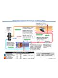
7 480 460 92 208 200 92. 440 84 190 83. 277 265 92 120 115 92. 254 84 110 84. 240 230 92. 220 84. 208 75. 200 69. 4. Electric Heater Sequence of Operation: 1. 120 Volt power from the control center (when supplied) or by others with out a control center, is delivered to the electric heater for the step controller. This power must be interlocked with the supply fan, so when the fan is off, the heater control power is off. 2. A thermostat with a duct stat is supplied. The duct stat is placed in the blower discharge and monitors the heated air. 3. Electric Heaters are divided in to equally sized steps. For example, a 100 KW heater with 5 steps will have 20 KW per step. The thermostat and step controller will control these steps. 4. A temperature and time delay of F and 2 seconds, respectively, is standard for the controller.
8 This is designed to prevent unncecessary cycling. 5. With the thermostat set to 70o F the heater will be off with a temperature sensing above 70o F. As the temperature varies the steps turn on and off to hold the setpoint discharge temperature. The colder the discharge temperature becomes the more steps the controller will energize. 6. In addition to the fan interlock mentioned in step 1, the heater has an airflow switch to prove that air flow is established before energizing the steps. The heater also has an automatic resetting highlimit switch and manual resetting highlimit switch set above the automatic switch to protect from overheating. Troubleshooting: Check-out Procedure: 1. Equipment Needed: a. Digital Voltmeter (0 - 20 VDC range) DVM. Input for intended use. May be Thermostat (HCC - 10K) or other input such as 0 - 13 ohm, 0 - 20 VDC, 0 - 20.
9 B. MA, 6 - 9 VDC, or 8 - 16 VDC. c. Output relays (loads) for output stages or 200 ohm, 5 watt resistor. 2. Wiring: a. Plug in the required number of 2 stage PC boards for application. (Stage boards always include two stages.). b. Connect output relays or 200 ohm, 5 watt resistor to provide output load. c. Program Input Switch to ON or OFF for seven positions provided. 5. Steam coils Application Recommendations: Satisfactory operation and service life are best ensured when coils are installed with proper piping, trap, and support arrangement. The following notes and figure 1 (page 7) are recommended for the coil unit installation and operation. General: 1. Provide separate supports and hangers for the unit and the piping. 2. Be certain that adequate piping flexibility is provided.
10 Stresses resulting form expansion of closely coupled piping and coil arrangement can cause serious damage. 3. Standard steam coils are pitched in the casings when installed for horizontal air flow. The CASING MUST. BE LEVEL after the unit is installed for proper condensate drainage. If condensate is not removed the coil will suffer from water hammering and will have a shortened life. On vertical air flow applications, the coils must be pitched when installed. 4. Do not reduce pipe size at the coil return connection. Carry return connection size through the dirt pocket, making the reduction at the branch leading to the trap. 5. It is recommended that vacuum breakers be installed on all applications to prevent retaining condensate in the coil. Generally, the vacuum breaker is to be connected between the coil inlet and the return main.