Transcription of GRINEL
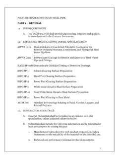
1 GRINNELL G-FIREF igure 522 Sprinkler Outlets Page 1 of 4 SEPTEMBER 2010 G230G-FIRET echnical Services 866-500-4768 | +1-401-781-8220 DescriptionThe GRINNELL Figure 522 Sprinkler Outlet is an economical alternative to welded pipe outlets on steel pipe. The Figure 522 Sprinkler Outlet may be used with full lengths of pipe and eliminates threading and welding, de-creasing waste and installation time. The Figure 522 Sprinkler Outlet may be used in wet pipe, dry pipe, and del-uge systems. WARNINGN ever remove any piping component nor correct or modify any piping de-ficiencies without first de-pressurizing and draining the system.
2 Failure to do so may result in serious personal injury, property damage, and/or impaired de-vice is the Designer s responsibility to se-lect products suitable for the intend-ed service and to ensure that pressure ratings and performance data are not exceeded. Material and gasket selec-tion should be verified to be compat-ible for the specific application. Always read and understand the installation GRINNELL Figure 522 Sprinkler Outlet described herein must be in-stalled and maintained in compliance with this document, as well as with the applicable standards of the Approval agency, in addition to the standards of any other authorities having jurisdic-tion.
3 Failure to do so may result in seri-ous personal injury or impair the per-formance of these are responsible for maintain-ing their mechanical system and devic-es in proper operating condition. The installing contractor or device manu-facturer should be contacted with any Data Approvals UL, FM, ULC, VdS, and LPCBM aximum Working Pressure300 psi (20,7 Bar)Sizes Run Sizes 1 , 1-1/4 , 1-1/2 , 2 , 2-1/2 , 76,1 mm Outlet Sizes ISO 7/1 or NPT Threaded 3/8 , 1/2 , 3/4 , 1 Housing MaterialsDuctile Iron conforming to ASTM A 536, Grade 65-45-12 Finish Zinc electroplate conforming to ASTM B 633 Type III Red (RAL3000)
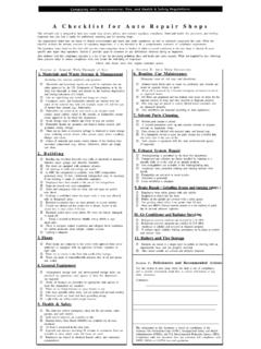
4 Painted finish for ISO Thread only Orange painted finish for NPT Thread onlyBoltsConforming to DIN 933, M8 x 30 mm Class Flange nuts conforming to DIN 934, Class 8 GasketGrade E EPDM, Green color code -30 F to 230 F (-34 C to 110 C) See Data Sheet G610 for additional gasket Loss Equivalent length of 1-Inch Schedule 40 pipe is 15 Williams coefficient = 120 For Fire Protection pressure rating, listing and approval information, contact Tyco Fire Suppression & Building 2 of 4 BCEADN ominal Pipe SizeOutlet SizeISO 7/1 or NPT ThreadsMax. Outlet End LoadLbs. (kN)Nominal Dimensions Inches (mm)Approx. Weight Lbs.
5 (kg)Nominal Run SizeANSI Inches (mm) ABCDE1 (33,7)1 (0,738) (25,4) (86,4) (49,3) (14,3) (25,4) (0,4)3 (1,156) (41,7) (86,4) (49,3) (29,0) (25,4) (0,5) (1,156) (46,5) (86,4) (57,2) (32,0) (25,4) (0,5)1-1 (42,4)3 (0,738) (31,0) (96,0) (57,2) (23,1) (26,9) (0,4)1 (0,738) (31,0) (96,0) (57,2) (19,8) (26,9) (0,4)3 (1,156) (46,5) (96,0) (57,2) (33,8) (26,9) (0,5) (1,81) (50,8) (96,0) (57,2) (36,6) (26,9) (0,6)1-1 (48,3)1 (0,738) (33,5) (101,6) (57,2) (22,4) (31,8) (0,5)3 (1,156) (49,0) (101,6) (57,2) (36,3) (31,8) (0,5) (1,81) (53,6) (101,6) (57,2) (39,4) (31,8) (0,6) (60,3)1 (0,738) (39,6) (113,3) (57,2) (28,4) (38,1) (0,6)3 (1,156) (55,1) (113,3) (57,2) (42,4) (38,1) (0,7) (1,81) (60,0) (113,3) (63,5) (45,5) (38,1) (0,7)2-1/2(DN65) (73,0)1 (0,738) (50,8) (130,0) (57,2) (39,6) (42,9) (0,7)3 (1,156) (63,5) (130,0) (57,2) (50,8) (42,9) (0,8) (1,81) (68,6) (130,0) (63,5) (54,4) (42,9) (0,8) (76,1)1 (0,738) (50,8) (130,0) (57,2) (39,6) (46,2) (0,7)3 (1,156) (63,5) (130,0) (57,2) (50,8) (46,2) (0,8) (1,81) (69,9) (130,0) (63,5) (55,6) (46,2) (0,8)
6 Maximum pressure and end load are total from all loads based on standard weight steel pipe. Pressure ratings and end loads may differ on other pipe materials and/or wall confirm compatibility by contacting Tyco Fire Suppression & Building Products for 1 FIGURE 522 SPRINKLER OUTLET NOMINAL DIMENSIONS G230 Page 3 of 4 Installation The GRINNELL Figure 522 Sprinkler Outlets are to be in-stalled in accordance with the following instructions. The 1 Inch (DN25) outlets can be used in fire protection sys-tems with a nipple leading directly to a sprinkler only. These fittings should be used for hydraulically calculated systems only.
7 Step 1. Verify hole size from Table A. The hole must be drilled on the pipe center-line. Remove any sharp or rough edges from the hole or upper housing contact area. The gasket-seating surface on the pipe should be examined to verify all loose debris, dirt, chips, paint and any other foreign material such as grease are that the gasket grade is cor-rect for the application intended. Refer to Technical Data Sheet G610 for additional gasket 2. Check for proper gasket po-sitioning in the housing. The align-ment tabs on the gasket should fit into the recesses of the housing. Check sealing surface for cuts or imperfections that would affect sealing.
8 For Wet Based applica-tions, no lubricant is required. When used for Dry Pipe and Freezer appli-cations, use a petroleum-free silicon based 3. With one nut and bolt re-moved and the other nut threaded out flush with the end of the screw, swing the housing over the hole in the 4. Verify that the housing out-let spike is positioned in the hole. Insert the other bolt into the hous-ing and rotate the nuts clockwise until finger tight. Verify that the bolt heads are fully seated in the housing. Step 5. Alternate when tightening nuts until properly torqued to be-tween 15 - 20 Lbs. (20-27 Nm) with even gaps between the bolt pads.
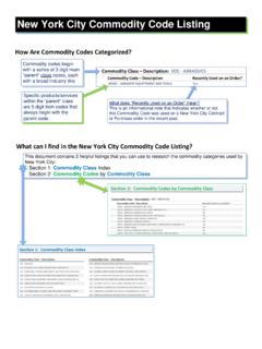
9 Uneven tightening can cause the gasket to pinch or bind. Over torquing can damage the product or thin wall pipe and will not increase sealing Run SizeANSI Inches DNNominal Branch SizeANSI Inches DNHole Diameter *Inches (mm)Tolerance +Inches (mm)1 DN251/2 / (24,0) (0,5)3/4 / DN201 / DN251-1/4 DN323/8 / DN101/2 / DN153/4 / DN201 / DN251-1/2 DN401/2 / DN153/4 / DN201 / DN252DN501/2 / DN153/4 / DN201 / / (34,9) mm DN651/2 / / (24,0)3/4 / DN201 / / (34,9)* Proper hole preparation is required for effective sealing and performance. Check the pipe seal surface within 5/8 of the hole to be certain it is free from conditions that would affect proper gasket sealing.
10 Remove any sharp or rough edges from the hole or upper housing contact area that might affect assembly, proper seating of the locating collar, or flow from the outlet. Check gasket grade to be certain it is suitable for the service. The use of threaded products other than steel pipe, such as dry pendants, etc. may not be compatible with the female threaded outlet on the Mechanical Tee. Always confirm compatibility by contacting GRINNELL A FIGURE 522 SPRINKLER OUTLET OUTLET HOLE DIMENSIONSG230 Page 4 of 4 Certified CompanyCopyright 2010 Tyco Fire Suppression & Building Products. All rights WarrantyProducts manufactured by Tyco Fire Suppression & Building Products (TFSBP) are warranted solely to the original Buyer for ten (10) years against defects in material and workmanship when paid for and properly installed and maintained under normal use and service.