Transcription of Ground Improvement by Stone Columns and Surcharge at a ...
1 Ground Improvement BY Stone Columns AND Surcharge AT A TANK SITE Kul Bhushan Ashok Dhingra Curt Scheyhing Group Delta Consultants, Inc. MWH, Inc. Group Delta Consultants, Inc. Aliso Viejo, California, USA Pasadena, California, USA Aliso Viejo, California, USA Endi Zhai Group Delta Consultants, Inc. Aliso Viejo, California, USA ABSTRACT The Ground Improvement performed at the site of two 190-ft ( m) diameter, 40-ft ( m) high, 8 million-gallon (30,300 m3), circular steel water storage tanks consisted of installation of Stone Columns to mitigate liquefaction and lateral spreading potential and a Surcharge program to reduce post-construction settlements. Settlement during the Surcharge program ranged between 9 and 15 in.
2 (225 and 375 mm) and post-construction settlement during the hydrotest was about inches (305 mm). INTRODUCTION Construction of two 190-ft ( ) diameter, 40-ft ( ) high, 8 million-gallon (30,300 m3), circular steel water storage tanks side-by-side on a 4-acre ( ) site was proposed. A geotechnical investigation by another firm originally recommended that tank foundations could be supported on 5 ft ( m) of recompacted onsite soils. This recommendation was apparently made assuming settlement of the tank was controlled by the load on the ring wall footing and 5 ft ( m) of removal and recompaction would be adequate. The fact that the primary loading is the weight of the water was not considered.
3 A review of the soil conditions by the authors disclosed significant geotechnical problems with the site including potential for large settlements, liquefaction, and lateral spreading. A subsequent investigation, which included drilling soil borings, Cone Penetration Tests (CPTs), and laboratory tests, confirmed that the site was underlain by highly compressible and potentially liquefiable soils. Also present were a 10-ft (3-m) deep channel and a detention pond in close proximity to the tank pad. The authors estimated that static settlements of more than 12 in. (305 mm) could occur under the tank loading. Also the potential for liquefaction and lateral spreading and resulting tank failure was high due to the presence of the adjacent channel and detention pond.
4 In lieu of costly pile foundations, the authors proposed an economical site Improvement plan which included installation of Stone Columns to mitigate liquefaction and lateral spreading potential and a soil Surcharge (preloading) to decrease post-construction settlement of the tanks. The measured settlements during the Surcharge ranged from 9 to 15 inches (228 to 375 mm). The Stone Columns densified loose granular soils, thereby mitigating liquefaction potential, and increased the average strength of the soft clays to improve the bearing capacity and mitigate lateral spreading potential. The tanks were successfully constructed and hydrotested. Measurements during hydrotest showed total settlements of about in.
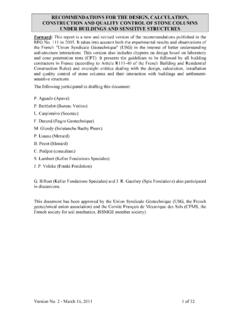
5 (305 mm) and differential settlements of inch ( mm). SITE & SUBSURFACE CONDITIONS Surface Conditions Surface site conditions relevant to the tank design are summarized below: The lot is roughly rectangular in shape, measuring about 560 ft (171 m) in the east-west direction and 330 ft (101 m) in the north-south direction. Site layout is shown in Fig. 1. The tank site has grades ranging between El. 33 to El. 35 feet ( to m). A new detention pond with a depth ranging from 6 to 10 ft ( to 3 m) and 3:1 (horizontal to vertical) side slopes was planned to be constructed about 25 ft ( m) south of the reservoirs. The site is bounded on the north, and along the northwest corner, by a 10-ft (3-m) deep concrete-lined drainage channel with vertical side retaining walls.
6 Paper No. 1 Downloaded from Fig. 1. Site Layout Table 1. Generalized Soil Profile Layer Number Depth (ft) Elevation (ft) Soil Type Undrained Strength1 (ksf) CPT Tip Resistance (tsf) Compressibility2,3,4 1 0-9 34 to 25 Stiff Clay / Silt (CL/ML) N/A E=600 ksf 2 9-20 25 to 14 Soft Highly Plastic Clay (CL/CH) to N/A Cr/(1+e0)=.02 Cc/(1+e0)=.17 3 20-25 14 to 9 Loose Sand (SM) N/A 60 E=360 ksf 4 25-40 9- to -6 Firm to Stiff Clay / Silt (CL-ML) > (avg. ) N/A Cr/(1+e0)=.007 Cc/(1+e0)=.07 5 40-52 -6 to -18 Medium Dense Sand / Silt (SM/ML) N/A 75 E=450 ksf 6 52-60 -18 to -26 Dense Sand (SP-SM) N/A 225 E=1350 ksf 7 60-63 -26 to -29 Stiff Clay / Silt (CL-ML) N/A E=700 ksf 8 63-76 -29 to -42 Dense Sand (SP-SM) N/A 200 E=1200 ksf 9 76-90 -42 to -56 Very Stiff Clay / Silt (CL-ML) N/A E=1000 ksf 10 90-96 -56 to -62 Very Dense Sand (SP-SM) N/A 325 E=2000 ksf NOTES: 1.
7 Undrained strength estimated from CPT (Nk=15). 2. Young s Modulus (E) for stiff clay estimated from correlations with undrained shear strength. 3. Young s Modulus (E) for sands estimated from correlations with CPT tip resistance. 4. Compressibility for soft to firm clay/silt based on interpretation of consolidation test results. 5. Groundwater at a depth of 10 to 16 ft (3 to m). 6. 1 ft = m, 1 ksf = kN/m2, 1 tsf = kN/m2. Paper No. 2 Paper No. 3 Subsurface Conditions Based on data from the borings and CPTs, the soil profile is relatively uniform. Beneath a cap of stiff clay/silt man-made fill soils, deep alluvial sediments underlie the site. Above El. 18 ft ( m), the alluvial sediments consist primarily of compressible soft to stiff clay/ silt layers, with isolated zones of loose to medium dense sands.
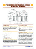
8 Below El. 18 ft ( m), the sediments consist of dense to very dense sands and stiff clays. We developed a generalized soil profile including strength and compressibility parameters shown in Table 1. A generalized cross-section illustrating the soil profile is shown in Fig. 2. The groundwater was present at depths ranging from 10 to 16 ft (3 to m) below existing grades. Seismic Conditions The site is located in a seismically active area of Southern California. Ground shaking due to nearby and distant earthquakes is anticipated during the life of the reservoirs. The closest active major fault to the site is the Newport-Inglewood Fault located about 4 miles ( km) from the project site.
9 This fault is a strike-slip fault with a maximum credible magnitude of The largest maximum credible Ground acceleration computed using deterministic methods and mean value of three attenuation relationships for the site was Probabilistic analyses indicated the following maximum Ground accelerations: Acceleration, g Probability of 10% 50% Exceedance 50-yr design life 100-yr design life Ground acceleration associated with 10% probability of exceedance in 50 years was selected for design. A peak Ground acceleration of g, including 20% increase for near-field effects, was used for liquefaction analyses and tank design. Fig.
10 2. Generalized Soil Profile Paper No. 4 Liquefaction and Lateral Spreading Liquefaction refers to loss of strength in a saturated granular soil due to buildup of pore water pressure during cyclic loading. When the pore water pressure becomes equal to the weight of the overlying soil, the soil is temporarily transformed into viscous fluid that is weaker than the non-liquefied material. For liquefaction to occur, three ingredients are required: 1. Liquefaction susceptible soils (loose to medium dense sand/silt) 2. Groundwater 3. Strong shaking, such as an earthquake Isolated zones of loose to medium dense sands below the groundwater table are present at the site, and could liquefy during the design earthquake.