Transcription of Grounding and Shielding - calex.com
1 A2401 stanwell Drive Concord, California 94520 Ph: 925/687-4411 or 800/542-3355 Fax: 925/687-3333 Email: and ShieldingThis article was written for CALEX by Mr. Ralph Morrison, President of INSTRUM and the author of Grounding and ShieldingTechniques in Instrumentation published by and Shielding of Amplifier,Bridgesensor and Voltsensor Input LeadsNoise can couple into low-level signals in a variety of coupling mechanisms involve not only the cable type butits shield and ground connections. The coupling is a systemproblem involving the amplifier, its bandwidth, the transducertype, the distances involved and the nature of the interferingsignals.
2 There are many ways to randomly connect shieldsand grounds but this rarely leads to an optimum set ofconnections. It is preferable to design a system based on anunderstanding of the coupling mechanisms and how to avoidtheir Sources1. Conducted InterferenceCurrents flowing in the ground system are a fact of life. Thesecurrents arise from the power system, from reactive couplingand from radiation. The resulting ground potential differencecan couple into the signal paths. It is usually futile to attemptto short out these potential differences. The two groundpoints of interest are the instrumentation power supply/outputtermination and the input lead termination.
3 This ground potentialdifference is usually referred to as Electromagnetic Field CouplingFields from nearby transmitters are often a source ofcontamination. These fields couple voltages into the inputcable in the form of a common-mode signal. The signal isproportional to loop area and to frequency. The loop area inquestion is between the cable and the earth plane. Normallythese signals are out of band and do not appear as are troublesome because they can be rectified in theinstrument and appear as a DC Magnetic Field CouplingMagnetic fields from fans, transformers or motors can inducevoltages into input cables.
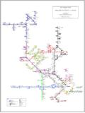
4 The leads carrying a signal must bevery close to the field source and they must open up to providea loop area for coupling. If reasonable care is taken to limitcoupling this noise source can usually be Capacitive CouplingElectric fields from nearby conductors can couple capacitivelyto signal leads. If the leads are shielded, the electric fieldsterminate on the shield and not on the input leads, and thisformFIGURE 1. A properly grounded input coupling can be greatly attenuated. Braid does not alwaysprovide full coverage and thus allows some electric fieldcoupling to shield itself is closely coupled to the input leads of a signalcable.
5 If the shield is connected improperly it can couplesignificant noise into the signal Transfer ImpedanceCurrent flowing in the shield can couple voltage to the conductorpair in a cable. This is generally a high frequency long lines some differential filtering may be needed toattenuate this type of Cable TreatmentTwo wire twisted and shielded cable is preferred for inputcable. The shield can serve as a guard, keeping externalfields from coupling to the signal leads. The signal is properlyguarded when the shield is connected to the zero referencepotential for the signal.
6 The only correct point for groundingthe shield is where the signal is grounded. If the signal isfloating then the shield must connect to one side of the amplifiers work best from grounded signal fact that the source ground and output ground differ inpotential is simply a common-mode rejection problem for theinstrument. This signal ground point should be where thetransducer is located. If not then the parasitic capacitancesbetween this ground and the transducer can couple noise intothe signal input cable shield cannot be grounded more than grounds create a shield gradient of potential.
7 If onetermination is correct then all other points on the shield areincorrect. The shield should be continuous along the entirepath. Openings in connectors or in distribution panels shouldbe kept to a minimum. A correctly configured input cable isshown in Figure 1. Note that the shield is not grounded at stanwell Drive Concord, California 94520 Ph: 925/687-4411 or 800/542-3355 Fax: 925/687-3333 Email: and ShieldingFIGURE a differential and common-mode filter to aninput 2. A proper connection for floating signal sourceFIGURE 3.
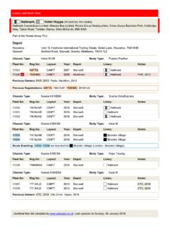
8 An improper shield connection for a floating sourceFloating SourcesUngrounded sources occur in instrumentation as a requirementfor safety or performance. The input circuitry of an instrumenthas a finite input current requirement. This current must returnto output ground. If this path is not provided, the instrumentmay appear to work but in reality it is functioning near a pointof saturation to create a return path for input current. Theproper way to provide for this current path is via a shield-to-ground resistor at the input. A resistor between the input leadsand the ground at the output invites noise current to flow in theinput leads and it also reduces the common-mode rejectioncapability of the instrument.
9 A proper circuit is shown inFigure that parasitic current still flows between the two groundsin capacitor C1 and resistor R3. Current flowing in R1, and R2is limited by the input impedance of the instrument. This alsolimits the common-mode rejection ratio. Figure 3 indicateswhat happens when the input shield is incorrectly potential difference between G1 and G2 drives current inthe loop C1, R2, and C2. Note that C2 is the capacitance in thecable between a signal conductor and the shield. Thisarrangement will be very noisy. Noise current flows in resistorR2 and the amplifier sees this as normal FiltersHigh frequency noise entering the amplifier can cause signalrectification.
10 This rectification causes DC offsets which areamplified as normal signal. The noise can enter both asnormal or common-mode components. Normal-mode ordifferential-mode signals can be filtered by a simple RC filterlocated at the input. Care must be taken to limit the seriesresistor to perhaps 500 ohms. Common-mode signals arebest attenuated by bypassing the shield to the local ground atthe signal interface. If the bypass path is too long it may be tooinductive to be effective. A filter arrangement is shown inFigure 4.