Transcription of Grounding in mixed-signal systems demystified, …
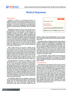
1 5 Analog Applications JournalTexas instruments Incorporated2Q 2013 High-Performance Analog ProductsGrounding in mixed - signal systems demystified , Part 2 This article is the second of a two-part series. Part 1 (see Reference 1) explained typical terminologies and ground planes and introduced partitioning methods. Part 2 dis-cusses the pros and cons involved in splitting the ground planes. It also explains Grounding in systems with multiple converters and multiple the ground planes are split and the traces are run across the split as shown in Figure 1, what will be the current return path? Assuming that the two planes are connected somewhere, usually at a single point, the return current has to flow in that large loop.
2 High-frequency currents flowing in large loops produce radiation and high ground inductance. Low-level analog currents flowing in large loops are susceptible to the two planes are connected only at the power supply (Figure 2), the return current is forced to flow all the way back to the power-supply ground, which is a really big loop! Also, the analog and digital ground planes, which are at different RF potentials and connected with long wires, unfortunately form a very effective dipole is preferred to have a continuous ground plane to avoid such long ground loops, but if it is absolutely neces-sary to have a split ground plane and traces are run across the split, the planes should first be connected at one loca-tion to form a bridge for the return current (Figure 3).
3 Routing all the traces so they cross at this bridge provides a return path directly underneath each of the traces, pro-ducing a very small loop area. A typical application of this method is a weighing scale where high-resolution ( 20-bit) delta-sigma analog-to-digital converters (ADCs) are options for passing the signal over a split plane are to use optoisolators (through light), transformers (through a magnetic field), or a true differential signal (where the signal flows down one trace and returns on the other trace with no ground needed for the return current).A better approach is partitioning. It is always prefera-ble to use only one ground plane, partitioning the PCB Data ConvertersBy Sanjay Pithadia, Analog Applications Engineer,and Shridhar More, Senior Analog Applications EngineerAnalog Ground PlaneDigital Ground PlaneFigure 1.
4 signal traces crossing a split on ground planeAnalog Ground PlaneDigital Ground PlanePowerSupplyFigure 2. Split planes connected at power supplyBridgeAnalog Ground PlaneDigital Ground PlaneFigure 3. Ground-plane bridge for tracesTexas instruments Incorporated6 Analog Applications JournalHigh-Performance Analog Products 2Q 2013 Data Convertersinto analog and digital sections (see Figure 4b). Analog signals must be routed only in the board s analog section, and digital signals must be routed only in the board s digital section, with both on all layers. Under these conditions, the digital return currents do not flow in the analog section of the ground plane and remain under the digital signal trace.
5 Figure 4 compares a split plane and a partitioned only problem with partitioning is that it is difficult when analog signals are improperly routed into the board s digital section, or vice versa (Figure 5). So for any PCB layout, the important points are to use a single ground plane, partition it into analog and digital sections, and apply discipline in when multiple data converters are used on a single boardMost datasheets for data converters discuss Grounding relative to a single PCB, usually the manu fac turer s own evaluation board. Usually the rec-ommendation is to split the PCB ground plane into an analog plane and a digital plane. It is further recommended that the analog ground (AGND) and digital ground (DGND) pins of a converter be tied together and that the analog and digital ground planes be connected at that same point, as shown in Figure 6.
6 This essentially creates the system s star ground point at the mixed - signal device. As explained in Part 1, all voltages in the circuit are measured with respect to this par-ticular point, not just to an unde-fined ground wherever one can clip a Ground PlaneDigital Ground PlaneFigure 4. Ground-plane layoutsDigital SectionAnalog SectionTracePartitioningGround Current(a) Split plane(b) Partitioned planeDigital SectionAnalog SectionTraceGround CurrentPartitioningFigure 5. Improperly routed digital signal traceAnalog ground plane sshapesame as for analog signal planeVDAGNDD igital groundplane s shapesame as for digital signal planeDGNDS ystem star groundconnections should beright below each mixed - signal device withminimal trace lengthsand no 6.
7 Grounding mixed - signal devices on a single PCBT exas instruments Incorporated7 Analog Applications Journal2Q 2013 High-Performance Analog ProductsData ConvertersAll noisy digital currents flow through the digital power supply to the digital ground plane and back to the digital supply, thus being isolated from the board s sensitive ana-log portion. The system s star ground point occurs where the analog and digital ground planes are joined together at the data converter. While this approach generally works in a simple system with a single PCB and a single data con-verter, it usually is not good for multicard and multicon-verter systems . If there are several data converters located on different PCBs, the concept breaks down because the analog and digital ground systems are joined at each con-verter on the PCB, creating ground a designer is working on an eight-layer PCB that has three DACs and two ADCs.
8 To minimize noise, the analog and digital ground planes should be connected together solidly under all the ADC and digital-to-analog converter (DAC) chips. The AGND and DGND pins should be connected to each other and to the analog ground plane, and the analog and digital ground planes should be connected individually back to the power supply. The power should enter the board in the digital partition and be fed directly to the digital circuitry, then filtered or regulated to feed the analog circuitry. Then only the digi-tal ground plane should be connected back to the power supply. Figure 7 shows the partitioned analog and digital ground planes and the power-supply connection for a PCB with multiple data mixed - signal systemsConfusion about mixed - signal Grounding has increased since designers started applying single-card Grounding concepts to multicard systems .
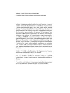
9 In systems having several data converters on different PCBs, the analog and digital ground planes are connected at several points, creating the possibility of ground loops and making a single-point star ground system best way to minimize ground impedance in a multi-card system is to use a motherboard PCB as a backplane for interconnections between cards. This provides a con-tin uous ground plane to the backplane. The PCB connector should have at least 30 to 40% of its pins devoted to ground. These pins should be connected to the ground plane on the backplane motherboard. To complete the over-all system Grounding scheme, there are two possibilities:1. The backplane s ground plane can be connected to the chassis ground at numerous points, thereby diffusing the various ground-current return paths.
10 This is com-monly referred to as a multipoint Grounding system (Figure 8).2. The ground plane can be connected to a single star ground point (generally at the power supply).The first approach is most often used in all-digital sys-tems but can also be used in mixed - signal systems , pro-vided that the ground currents from digital circuits are sufficiently low and diffused over a large area. The low PartitioningAnalogDevicesDigitalDevicesD igitalPowerDigital SectionAnalog SectionAnalog PowerDigitalPowerFilterADCADCADCF igure 7. Power and ground for PCB with multiple ADCsBackplane GroundChassisGroundPowerSuppliesBoard 1 Board xGND PlaneGND Plane..Figure 8. Grounding scheme for multicard systemTexas instruments Incorporated8 Analog Applications JournalHigh-Performance Analog Products 2Q 2013 Data Convertersground impedance is maintained all the way through the PCBs, the backplane, and ultimately the chassis.