Transcription of GROUTING CONCRETE MASONRY WALLS TEK 3-2A
1 TEK 3-2A 2005 National CONCRETE MASONRY Association (replaces TEKs 3-2 and 3-3A)NCMA TEKN ational CONCRETE MASONRY Associationan information series from the national authority on CONCRETE MASONRY technologyGROUTING CONCRETE MASONRY WALLSTEK 3-2 AConstruction (2005)Keywords: cleanouts, CONCRETE MASONRY units, construc-tion techniques, consolidation, demonstration panel,grout, GROUTING , lift height, pour height, puddling,reinforced CONCRETE MASONRY , reinforcementINTRODUCTIONG routed CONCRETE MASONRY construction offers designflexibility through the use of partially or fully grouted WALLS ,whether plain or reinforced. The industry is experiencingfast-paced advances in GROUTING procedures and materials asbuilding codes allow new opportunities to explore means andmethods for constructing grouted MASONRY is a mixture of: cementitious material (usuallyportland cement); aggregate; enough water to cause the mix-ture to flow readily and without segregation into cores orcavities in the MASONRY ; and sometimes admixtures.
2 Grout isused to give added strength to both reinforced and unrein-forced CONCRETE MASONRY WALLS by GROUTING either some or allof the cores. It is also used to fill bond beams and occasionallyto fill the collar joint of a multi-wythe wall. Grout may also beadded to increase the wall's fire rating, acoustic effectivenesstermite resistance, blast resistance, heat capacity or anchor-age capabilities. Grout may also be used to stabilize screenwalls and other landscape reinforced MASONRY , grout bonds the MASONRY unitsand reinforcing steel so that they act together to resistimposed loads. In partially grouted WALLS , grout is placedonly in wall spaces containing steel reinforcement. When allcores, with or without reinforcement, are grouted, the wall isconsidered solidly grouted. If vertical reinforcement isspaced close together and/or there are a significant numberof bond beams within the wall, it may be faster and moreeconomical to solidly grout the for grout, sampling and testing proce-dures, and information on admixtures are covered in Grout forConcrete MASONRY (ref.)
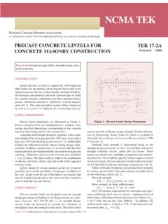
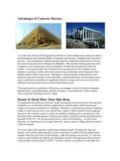
3 1). This TEK covers methods forlaying the units, placing steel reinforcement and CONSTRUCTIONF igure 1 shows the basic components of a typical rein-forced CONCRETE MASONRY wall. When WALLS will be grouted, CONCRETE MASONRY units must be laid up so that vertical coresare aligned to form an unobstructed, continuous series ofvertical spaces within the 1 Typical Reinforced CONCRETE MASONRY Wall SectionCells containing reinforcement are filled solidly with grout; vertical cells should provide a continuous cavity, substantially free of mortar droppingsPlace mortar on cross webs adjacent to cells which will be groutedVertical reinforcement - lap and secure as requiredReinforcement in bond beams is set in place as wall is laid upPlace mesh or other grout stop device under bond beam to confine grout or use solid bottom unitDrip edgeFlashingLeave this block out to serve as a cleanout until wall is laid upHead and bed joints must be filled with mortar for thefull thickness of the face shell.
4 If the wall will be partiallygrouted, those webs adjacent to the cores to be grouted aremortared to confine the grout flow. If the wall will be solidlygrouted, the cross webs need not be mortared since the groutflows laterally, filling all spaces. In certain instances, fullhead joint mortaring should also be considered when solidgrouting since it is unlikely that grout will fill the spacebetween head joints that are only mortared the width of theface shell, , when penetration resistance is a concern suchas torm shelters and prison WALLS . In cases such as those,open end or open core units (see Figure 3) should beconsidered as there is no space between end webs with thesetypes of should be taken to prevent excess mortar fromextruding into the grout space. Mortar that projects more than1/2 in. (13 mm) into the grout space must be removed (ref.)
5 3).This is because large protrusions can restrict the flow of grout,which will tend to bridge at these locations potentially causingincomplete filling of the grout space. To prevent bridging,grout slump is required to be between 8 and 11 in. (203 to 279mm) (refs. 2, 3) at the time of placement. This slump may beadjusted under certain conditions such as hot or cold weatherinstallation, low absorption units or other project specificconditions. Approval should be obtained before adjusting theslump outside the requirements. Using the grout demonstra-tion panel option in Specification for MASONRY Structures(ref. 3) is an excellent way to demonstrate the acceptability ofan alternate grout slump. See the Grout Demonstration Panelsection of this TEK for further the footing, mortar bedding under the first course ofblock to be grouted should permit grout to come into directcontact with the foundation or bearing surface.
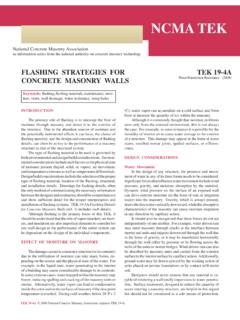
6 If foundationdowels are present, they should align with the cores of themasonry units. If a dowel interferes with the placement of theunits, it may be bent a maximum of 1 in. (25 mm) horizontallyfor every 6 in. (152 mm) vertically (see Figure 2). When wallswill be solidly grouted, saw cutting or chipping away a portionof the web to better accommodate the dowel may also beacceptable. If there is a substantial dowel alignment problem,the project engineer must be reinforcing steel may be placed before theblocks are laid, or after laying is completed. If reinforcementis placed prior to laying block, the use of open-end A or H-shaped units will allow the units to be easily placed around thereinforcing steel (see Figure 3). When reinforcement is placedafter wall erection, reinforcing steel positioners or otheradequate devices to hold the reinforcement in place arecommonly used, but not required.
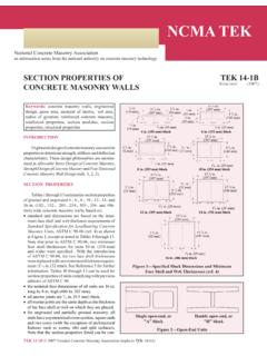
7 However, it is requiredthat both horizontal and vertical reinforcement be locatedwithin tolerances and secured to prevent displacement duringgrouting (ref. 3). Laps are made at the end of grout pours andany time the bar has to be spliced. The length of lap splicesshould be shown on the project drawings. On occasion theremay be locations in the structure where splices are locations are to be clearly marked on the drawing. Reinforcement can be spliced by either contact ornoncontact splices. Noncontact lap splices may be spaced as farapart as one-fifth the required length of the lap but not more than8 in. (203 mm) per Building Code Requirements for MasonryStructures (ref. 4). This provision accommodates constructioninterference during installation as well as misplaced 3 CONCRETE MASONRY Units forReinforced ConstructionFigure 2 Foundation Dowel ClearanceDowels may be bent up to 1 in.
8 (25 mm) laterally per 6 in. (152 mm) verticallyVertical reinforcement, as requiredConcrete MASONRY wallConcrete foundationGrout, as requiredLintel unitDouble open end or "H" shaped unitPilaster unitsOpen end, or "A" shaped unitBond beam unitsOpen core unitSplices are not required to be tied, however tying is often usedas a means to hold bars in the wall is constructed, horizontal reinforcementcan be placed in bond beam or lintel units. If the wall will notbe solidly grouted, the grout may be confined within thedesired grout area either by using solid bottom masonrybond beam units or by placing plastic or metal screening,expanded metal lath or other approved material in thehorizontal bed joint before laying the mortar and units beingused to construct the bond beam. Roofing felt or materialsthat break the bond between the MASONRY units and mortarshould not be used for grout MASONRY UNITS ANDREINFORCING BARSS tandard two-core CONCRETE MASONRY units can beeffectively reinforced when lap splices are not long, since themason must lift the units over any vertical reinforcing bars thatextend above the previously installed MASONRY .
9 The concretemasonry units illustrated in Figure 3 are examples of shapesthat have been developed specifically to accommodatereinforcement. Open-ended units allow the units to be placedaround reinforcing bars. This eliminates the need to threadunits over the top of the reinforcing bar. Horizontalreinforcement in CONCRETE MASONRY WALLS can beaccommodated either by saw-cutting webs out of a standardunit or by using bond beam units. Bond beam units aremanufactured with either reduced webs or with knock-out webs, which are removed prior to placement in the and column units are used to accommodate a wall-column or wall-pilaster interface, allowing space for verticalreinforcement and ties, if necessary, in the hollow MASONRY units should meet applicable ASTM standards and should typically be stored on pallets to preventexcessive dirt and water from contaminating the units.
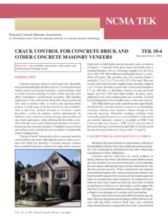
10 Theunits may also need to be covered to protect them from rainand primary structural reinforcement used in concretemasonry is deformed steel bars. Reinforcing bars must be ofthe specified diameter, type and grade to assure compliancewith the contract documents. See Steel Reinforcement forConcrete MASONRY , TEK 12-4C for more information (ref. 6).Shop drawings may be required before installation can rust, mill scale or a combination of both need notbe removed from the reinforcement. Mud, oil, heavy rust andFigure 4 Comparison of GROUTING Methods for a 12 ft-8 in. (3,860 mm) High CONCRETE MASONRY WallGrouting without cleanouts: GROUTING with cleanouts: GROUTING with cleanouts per(Low-lift)(High-lift)MSJC (2005) or grout demonstration panel:No cleanouts requiredCleanouts requiredCleanouts requiredWall built in 3 stagesWall built full heightWall built full heightBars spliced at pour heightBars installed full length (no splicing)Bars installed full length (no splicing)Three grout liftsThree grout liftsOne grout lift2 ft 8 in.