Transcription of GRUNDFOS INSTRUCTIONS - California Institute of …
1 GRUNDFOS INSTRUCTIONS . CHI and CHIE Series Stainless Steel Horizontal Multistage End Suction Pumps Installation and operating INSTRUCTIONS CONTENTS As standard, the mechanical shaft seal for the CHI pump is available in six versions with different material combinations; see the stamping code on the pump nameplate. 1. Pre-installation Checklist 2 Example: Type CHI 4-50 A-B-G-BQQE. 2. General data 2. 3. Technical data 2 Shaft seal materials Code 4. Installation 3 Seal faces Rubber parts 5. Electrical connections 3 BUBE Tungsten carbide/ EPDM. 6. CHIE-Plus Additional INSTRUCTIONS 3 BUBV carbon FKM. 7. Start-up 3 BQQE EPDM. SiC/SiC*. BQQV FKM. 8. Operation and Maintenance 4. BUUE Tungsten carbide/ EPDM. 9. Preliminary Checks 4 BUUV Tungsten carbide FKM. 10. Fault-finding chart 4 *SiC: Silicon carbide. 11. Disposal 4. Before beginning installation procedures, these installation and 3. Technical data operating INSTRUCTIONS should be studied carefully. The installation and operation should also be in accordance with Ambient temperature local regulations and accepted codes of good practice.
2 +5 F to +104 F (-15 C to +40 C) at a relative air humidity of maximum 95%. PLEASE LEAVE THESE INSTRUCTIONS WITH THE. PUMP FOR FUTURE REFERENCE. Liquid temperature +5 F to +230 F (-15 C to 110 C). Maximum operating pressure 1. Pre-installation Checklist 145 psi (10 bar). Confirm you have the right pump Maximum Inlet Pressure Read the pump nameplate to make sure it is the one you ordered. The actual inlet pressure plus the pressure when the pump is operating against a closed valve should always be lower than the maximum operat- Check the condition of the pump ing pressure.. The shipping carton your pump came in is specially designed around your pump during production to prevent damage. As a precaution, it should Sound pressure level remain in the carton until you are ready to install it. At that point look at The sound pressure level of the pump is less than 70 dB(A) at a distance of the pump and examine it for any damage that may have occurred during 3 feet from the pump.
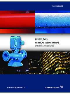
3 Shipping. 2. General data 4. Installation Pump location CHI & is the difference? The pump must be installed with the motor shaft horizontal, see fig. 1, CHI and CHIE pump end components are identical. The difference and so that adequate air supply reaches the motor cooling fan. between the two models is the stator and terminal box. CHI pumps are standard 1 phase and 3 phase, 60 HZ, constant speed pumps. CHIE and Fig. 1. CHIE-Plus pumps are powered by 1 phase, 230 volts, 60 HZ, variable speed A solid foundation should be provided for motors with an integrated variable frequency drive (VFD) and system the pump, which can be secured by bolts, if Discharge Port controller ( PI type). Consult the GRUNDFOS Installation and required. Operating INSTRUCTIONS , included with the pump, for electrical installation Pipe connections: and motor operation. Refer to these INSTRUCTIONS for pump end installation Suction and discharge ports: and operation. CHI 2: 1 NPT. Applications CHI 4: 1 1/4 NPT.
4 CHI 8: 1 1/2 NPT. GRUNDFOS pumps, type CHI, are horizontal multi-stage centrifugal pumps CHI 12: 1 1/2 NPT. of the non-self-priming type designed for pumping thin non-explosive liquids. Suction Port CAUTION - This pump is intended for use Install the pipes so that air pockets are avoided, especially on the suction with water only. side of the pump, shown in fig. 2. Fig. 2. The pump with integral motor is fitted to a base plate. The pump is made of corrosion-resistant materials, which makes it ideally suited for water supply and a wide range of applications in industry, agriculture and in the food industry. TM00 2263 0195. The pump must not be used for the transfer of flammable liquids such as diesel oil, gasoline, or similar liquids. The pump is designed for pumping clean water, domestic hot water, aqueous solutions, cleaning solutions, suspensions or light oils and other Isolating valves should be fitted on either side of the pump to avoid liquids with a density and viscosity corresponding to those of water.
5 The draining the system if the pump needs to be cleaned or repaired. liquids must not contain abrasive particles or fibers. If pumps are installed close to living accommodation, it is advisable to fit When pumping liquids with a density or viscosity higher than that of anti-vibration mountings on either side of the pump and between the water, motors with correspondingly higher outputs must be used. foundation and pump to prevent vibration being transmitted through the pipework. This applies especially to pumps installed in concrete buildings. 2. Install the pump so that it is not stressed or strained by the pipework, Install the check valve at or near the suction port and a pressure gauge especially tension caused by variations in temperature. If pumps are down line from the pump discharge. installed in long pipes, these should be adequately supported before and Prime the pump through the priming plug on the cross fitting. after the pump. At start-up, make sure fluid is supplied to the inlet of the pump.
6 Adjust If there is any danger of the pump running against a closed valve in the the pump by pressing the + or - buttons until the desired setpoint is discharge pipe, a bypass should be installed on the discharge side of the achieved. Open the priming plug slightly to allow residual air to escape. pump to ensure that adequate cooling and lubrication water is circulated If the fluid is something other than water, take care to make sure through the pump (a minimum flow equal to 10% of the nominal flow is escaping air/fluid does not cause harm to the installer or adjacent needed at all times). equipment. Tighten the priming plug. This is less for CHIE pumps. CHIE pumps can automatically stop at no-flow To test the stop function, close the pump discharge (isolation valve or conditions. demand fixtures). The pump should stop within two minutes. If it does not stop, check for plumbing leaks. 5. Electrical connections To test the constant pressure function, open the discharge slightly and adjust the + or - buttons to the desired setpoint.
7 As the flow is The electrical connection and protection should be carried out in varied, the pump will change speed to maintain the desired pressure. If accordance with local regulations. The connections are shown in the the pressure drops as you increase the flow, you may have exceeded the wiring diagram inside the terminal box cover. maximum capacity of the pump. The desired pressure is only maintained when the demand point is Never make any connections in the pump terminal box unless under the maximum pump curve. the electricity supply has been switched off. The pump must be connected to an external main switch. 7. Start-up The operating voltage and frequency are marked on the nameplate. Please At high system temperatures, the pump may be extremely hot. make sure that the motor is suitable for the electricity supply on which it Do not touch it. will be used. CHI single-phase motors DO NOT incorporate a thermal overload switch and require additional motor protection.
8 (CHIE motors do not require this, Priming only fuses or circuit breakers per INSTRUCTIONS in the Installa- Before startup, or if the pump has been drained, the pump must be filled tion and Operating INSTRUCTIONS . ) with liquid and vented. Proceed as follows: Three-phase motors must be connected to an approved motor starter. The In closed systems or open systems where the liquid level is above the set nominal current of which must correspond to the electrical data on the pump inlet: pump nameplate. 1. Close the discharge isolating valve. Do not start the pump until it has been filled with liquid. 2. Remove the priming plug in the pump sleeve, see fig. 5. Connections should be made as shown on the inside of the terminal Slowly open the isolating valve in the suction pipe until a steady stream of box cover. liquid runs out of the priming port. Choose one of the two CHI cable entries and knock out the pre-cut disk. CHIE INSTRUCTIONS are in the Installation and Operating INSTRUCTIONS .
9 The escaping liquid may be scalding hot. Therefore, care must be taken to ensure that the liquid does not cause personal injury or damage to other components. On pumps with the base plate fitted to the pump, the terminal box can be turned to three positions, in 90 steps, see fig. 3. To change the position of the terminal box, proceed as follows: 3. Start the pump and slowly open the discharge valve until it is fully 1. Remove the four screws securing the motor to the motor stool. open. 2. Turn the motor to the required position. 4. Completely open the isolating valve(s). Replace and tighten the four screws. Fig. 5. Fig. 3 Priming plug G 3/8. 0 . TM00 5929 2000. TM00 5927 0697. 270 90 . Drain plug G 3/8. In open systems where the liquid level is below the pump inlet, the suction pipe must also be filled with liquid and vented before the pump Pumps with the base plate fitted to the motor must be installed with the is started: terminal box in position 0 , see fig.
10 4. 1. Close the discharge isolating valve. Fig. 4 2. Remove the priming plug in the pump sleeve. 0 3. Pour water through the priming hole until the suction pipe and the pump are completely filled with liquid. - If the suction pipe does not slope downwards away from the pump, TM00 5926 1300. air must be purged from the suction pipe while the pump is being filled. - Filling may take place at the highest point of the suction pipe if this is above the priming plug of the pump. 4. Replace the priming plug and tighten securely. Checking direction of rotation (CHI three-phase). 6. CHIE-Plus Additional INSTRUCTIONS Arrows on the fan cover indicate the correct direction of rotation. The pump should rotate counter-clock-wise when seen from the motor fan. To Attach the transducer/tank assembly to the pump. The mating reverse rotation, switch off electricity supply and interchange any two of half-union is already installed on the pump. Position the assembly such the incoming supply wires.