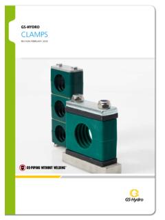
Transcription of GS-HYDRO GS-FLANGE SYSTEM
1 GS-HYDROGS- flange SYSTEMREVISION FEBRUARY 2016 PRODUCT CATALOGUE GS-FLANGE SYSTEM INTRODUCTION3 INTRODUCTIONINTRODUCTION ..3 610-40 BAR ..7 10 SAE 50 BAR ..11 32 SAE 3000 PSI (ISO 6162-1) ..33 76 SAE 6000 PSI (ISO 6162-2) ..77 124350 400 BAR (ISO 6164) ..125 156 SAE 10000 PSI ..157 166 TECHNICAL INFORMATION ..167 186GS-Hydro is the world s leading supplier of non-welded piping systems. Operations began in 1974 with the commercialization of an innovative flange , which allowed the rapid and secure connection of pipes without the need for welding. Investing in continuous product and systems development, GS-HYDRO now offers the broadest range of non-welded piping solutions on the market. Our core technology has been validated in thousands of applications for over four decades and has been taken to virtually every corner of the main application for our technology is in hydraulics, where the high pressures place stringent requirements on pipe connections.
2 However, we also meet the needs of all markets where customer requirements demand any one of the many benefits our technology provides over welding, such as superior cleanliness, serviceability, prefabrication, rapid installation or zero-fire ORIGINAL GS-Piping SYSTEM consists of three flange systems, which allow piping systems with working pressures from 10 to 690 bar and pipe diameters between 16 and 600 mm to be assembled without welding. The Retain Ring and 37 Flare flange systems are used for high pressure connections and the 90 Flare flange connection for low pressure in briefMain indexPRODUCT CATALOGUE GS-FLANGE SYSTEM INTRODUCTION 4 GS flange connectionsRetain Ring SystemThe GS Retain Ring SYSTEM is used for piping with a maximum allowable working pressure up to 350 400 bar. In special applications, the retain ring SYSTEM can be used with working pressures as high as 690 bar. Extensive testing programs have shown the suitability of the retain ring jointing method for high pressure piping systems in a wide range of different materials ranging from carbon and stainless steel to duplex and titanium and all other quality pipe materials with an elongation above 20%.
3 SAE 50 SAE 3000 SAE 6000 ISO 6164pressure [bar]50210 350420210 690size, pipe50x3 273x626x6 97x1226x6 , flange1 1/2 10 1/2 3 1/2 3 2 14 material, pipecarbon steel, galvanised steel, duplex, super duplex, titanium (materials having elongation above 20%)material, flangeelectric zinced carbon steel, hot dip galvanized carbon steel, stainless steel or titanuimmaterial, sealNBR, FPM (Viton )material, retain ringstainless steel37 Flare flange SYSTEM The 37 flare flange SYSTEM is used for piping with a maximum allowable working pressure of 420 bar. The 37 flare flange jointing method is suitable for high pressure piping systems in a wide range of different materials ranging from carbon steel to 50 SAE 3000 SAE 6000 ISO 6164 pressure [bar]50210 350420350 400size, pipe50x3 273x616x2 90x516x2 90x950x5 90x9size, flange1 1/2 10 1/2 3 1/2 3 1 1/2 3 material, pipecarbon steel, galvanised steel, copper-nickel, aluminium/brass duplex, super duplex, titanium, tungum (materials having elongation above 20%)material, flangeelectric zinced carbon steel, hot dip galvanized carbon steel, stainless steelmaterial, sealNBR, FPM (Viton )90 Flare flange SYSTEM The 90 flare flange SYSTEM is used for class III piping with a maximum allowable working pressure of 16 bar.
4 The 90 flare flange jointing method is suitable for low pressure piping systems in a wide range of different materials ranging from carbon steel to super duplex. SAE ANSI/JIS/BS/DIN/COST pressure [bar]10 4010 40size, , flange1/2 8 1/2 24 material, pipecarbon steel, galvanised steel, copper-nickel, aluminium/brass duplex, super duplex, titanium, tungum (materials having elongation above 20%)material, flangeelectric zinced carbon steel, hot dip galvanized carbon steel, stainless steel or titaniummaterial, sealbased on media inside pipe (example Klinger SIL C-4430)PRODUCT CATALOGUE GS-FLANGE SYSTEM INTRODUCTION5 INTRODUCTIONGS-pressure classesGS-Hydro s flange systems are divided into pressure classes. The pressure class is selected based on the working pressure of the piping SYSTEM . Each pressure class contains then all the GS-components needed for the piping SYSTEM with that specific working pressure.
5 10 40 bar 90 flare flanges and sealings SAE 50 bar SAE-dimensioned low pressure piping components for 37 flaring and retain ring connection SAE 3000 psi Components for metric pipes and connection components for schedule series pipes according to SAE-standard J518C code 61 SAE 6000 psi Components for metric pipes and connection components for schedule series pipes according to SAE-standard J518C code 62 350 400 bar Components for metric pipes and connection components for schedule series pipes according to ISO 6164 standard SAE 10000 psi Components for schedule series pipes drilled to SAE-standard J518C code 62 Type ApprovalsGS-Hydro flange systems are type approved by the following classification companies: Institute37 Flaring50 420 barRetain Ring50 420 barRetain Ring690 bar90 FlaringDNV Det Norske Veritas ClassificationxxxxLR Lloyds Register MEAxxxGL Germanischer LloydxxxABS American Bureau of ShippingxxxBV Bureau VeritasxxxRINA Registro Italiano NavalexxxMRS Russian Maritime Register of ShippingxxxNKK Nippon Kaiji KyokaixxxCCS China Classification SocietyxxxKR Korean RegisterxxxType approvals and pressure classesPRODUCT CATALOGUE GS-FLANGE SYSTEM INTRODUCTION 6 flange Code Face TypePressureSize1 ISO 6162-150 bar1 1/2 5 1/2round50 bar6 10 3 ISO 6162-1210 bar (3000 psi)1/2 3 6 ISO 6162-2420 bar (6000 psi)1/2 3 08 1216202432401/2 3/4 1 1 1/4 1 1/2 2 2 1/2 485660648096283 3 1/2 3 3/4 4 5 6 8 38X4 Pipe x wall thickness [mm]Insert Cone Code Sealing SurfaceFAO-ring grooveFBFlat faceFCBonded seal grooveFDStraight couplingPart NoPipe SizeInsert Cone Code316/38X4FC*GS-size code*)
6 316/38X4FC includes:316F 1 pc16/38X4FC 1 pc1629 1 1 pc432019* flange Code Face TypePressureSize1 ISO 6162-150 bar1 1/2 5 1/2round50 bar6 10 3 ISO 6162-1210 bar (3000 psi)1/2 3 4 ISO 6164400 bar2 4 6 ISO 6162-2420 bar (6000 psi)1/2 3 8round210 350 bar4 1/2 14 9 ISO 6162-2690 bar (10000 psi)1/2 3 (8 )Part No08 1216202432401/2 3/4 1 1 1/4 1 1/2 2 2 1/2 4856606480961603 4 4 1/2 5 6 8 10 224 224 14 GS-size code*) 432019 includes:432 2 pcs32019 1 pc32 2 pcs3219 2 pc001 flange for welding022 Hose insert, 45 002 flange for welding035 Tee between (BSP 1/4 )003 flange for welding036 Tee between (BSP 1/2 )004 flange for welding037 Tee between (BSP 3/4 )005 flange for welding082 flange for welding006 flange for welding083 flange for welding007 flange for welding084 flange for welding008 flange for welding085 flange for welding009 flange for welding086 flange for welding010 flange for welding099 Adaptor011 flange for welding113 Female thread flange (NPT)013 Female thread flange (BSP)114 Male thread flange (NPT)014 Male thread flange (BSP)115 Elbow block015 Elbow flange116 Tee block016 Tee flange125 Blind flange018 flange bend129 Ball valve flange019 Bulkhead flange135 Non-return valve020 Hose insert, straight150 Tailstock021 Hose insert, 90 214 Male thread flange (UNF)
7 DesignationGS-code key 37 flare flange connectionGS-code key retain ring flange connectionPRODUCT CATALOGUE GS-FLANGE SYSTEM 10-40 BAR7 10 40 BARGS-90 Flare flanges Drilled to SAE J 518 Code 61 ..8GS-90 Flare flanges for DIN 2501 ..9GS-90 Flare flanges for ANSI Class 150 CATALOGUE GS-FLANGE SYSTEM 10-40 BAR8 GS-90 Flared flange 16 barDrilled to ISO 6162-1 (SAE J 518 Code 61)SizePipe noID CodeA BGHW eight[kg]BoltDIN 912, NoGasketID Code1/2 25308N110500209017,538,146540,2M8 x 5533,05551592008NG27012990003/4 30312N110500210022,247,652660,2M10 x 6041,56357702012NG27012992001 38316N110500211026,252,459700,2M10 x 6547,36964752016NG27012994001 1/4 42320N110500212030,258,773790,4M10 x 6554,08178842020NG27012996001 1/2 50124N110500110035,769,983940,5M12 x 7065,39387992024NG27013000002 60132N110500111042,977,8971020,7M12 x 7076,01041021072032NG27013020002 1/2 73140N110500114050,888,91091140,8M12 x 7090,01171141202040NG27013030003 90148N110500116061,9106,41311351,4M16 x 80106,61381361412548NG27013040004 115164N110500118077,8130,21521622,0M16 x 90135,01621571683064NG27013060005 140180N110500119092,1152,41801843,2M16 x 110161,51881861904080NG2701307000 TUN6 165196N1105001220208,0236,06,2M16 x 100191,564096NG27013080008 220228N1105001230275,0317,011M20 x 120254,084028NG2701301000 Material possibilities.
8 Standard= carbon steel, zinc platedCarbon steel, hot dip galvanized= add HDG after Part NoStainless steel= add SS after Part NoOther materials and pipe sizes on material:Standard= KlINGErSIl C-4430 Other materials on 228 NAHNMGOB308N 180 NPort dimensions for flange connections according to ISO d maxManufacturing tolerance for flange thickness (S) 5%.PRODUCT CATALOGUE GS-FLANGE SYSTEM 10-40 BAR9 10 40 BARPart numbers for three different surface treatment (others on request): - Standard plain metal without coating- HDG hot dip galvanized (add HDG after Part No)- ZN electric zinced (add ZN after Part No)Component material: Carbon steel S235, other materials on flange to flange (L)= flange to blockSKTSizePipe [mm]Part NoStandardID CodeStandardID CodeHDG-surfaceID CodeZN-surfacePN 10/40 Weight[kg]Gasket Part NoGasket ID CodeTKSB olts DIN 9311 1/4 1116103100 1106303100 140100184 x M16x60(40) 1116103200 1106303200 140100184 x M16x60(40) 1/2 1116104000 1106304000 150110184 x M16x60(40) 1116104100 1106304100 150110184 x M16x60(40) 1116105100 1106305100 165125204 x M16x70(45) 1116105200 1106305200 165125204 x M16x70(45) 1/2 1116106000 1106306000 185145204 x M16x70(45) 1116106100 1106306100 185145204 x M16x70(45) 1116106200 1106306200 185145228 x M16x70(45) 1116106300 1106306300 185145228 x M16x70(45) 1116107000 1106307000 200160208 x M16x70(45) 1116107100 1106307100 200160248 x M16x80(45)
9 1116108000 1106308000 220180228 x M16x70(45) 1116108100 1106308100 220180228 x M16x70(45) 1116108200 1106308200 235190268 x M20x90(55) 1116109000 1106309000 250210228 x M16x80(45) 1116109100 1106309100 250210228 x M16x80(45) 1116109200 1106309200 270220288 x M24x100(65) 1116110000 1106310000 285240248 x M20x80(55) 1116110100 1106310100 285240248 x M20x80(55) 1116110200 1106310200 300250308 x M24x100(65) 1116111000 1106311000 340295248 x M20x90(60) 1116111100 1106311100 3402952612 x M20x90(60) 1116111200 1106311200 3603103212 x M24x110(70) 1116112000 1106312000 3953502612 x M20x90(60) 1116112100 1106312100 4053552912 x M24x100(70) 1116112200 1106312200 4454002612 x M20x90(60) 1116113000 1106313000 4604103212 x M24x110(70) 1116113100 1106313100 5054603016 x M20x100(65) 1116113200 1106313200 5204703516 x M24x120(75) 1116114000 11063140005655153216 x M24x110(70) 1116114100 1106314100 5805253816 x M27x130(80) to EN 1092-1 (DIN 2501)Gasket material:Standard= KLINGERSIL C-4430 Other materials on Flared flange for DIN 2501 Manufacturing tolerance for flange thickness (S) 5%.
10 PRODUCT CATALOGUE GS-FLANGE SYSTEM 10-40 BAR10 Component material: - Carbon steel S235, other materials on treatment: - Hot dip galvanized, others on requestSKTSizePipe [mm]Part NoID CodeANSI Class 150 psi FlangesWeight[kg]Gasket Part NoGasket ID CodeTKSStud bolts1/2 x 1/2 x 55 x 1/2 x 55 x 1/2 x 65 x 1/2 x 65 x 1/2 x 65 x 1/2 x 65 1/4 x 1/2 x 70 x 1/2 x 70 1/2 x 1/2 x 70 x 1/2 x 70 x 5/8 x 85 x 5/8 x 85 1/2 x 5/8 x 90 x 5/8 x 90 x 5/8 x 90 x 5/8 x 90 x 5/8 x 90 x 3/4 x 95 x 3/4 x 95 x 3/4 x 100 mm x 3/4 x 100 x 3/4 x 110 x 7/8 x 115 x 7/8 x 115 x 7/8 x 120 x 1 x 135 x 1 x 135 x 1 x 135 x 1 x 135 to ANSI B material:Standard= KLINGerSIL C-4430 Other materials on Flared flange for ANSI Class 150 psiManufacturing tolerance for flange thickness (S) 5%.PRODUCT CATALOGUE GS-FLANGE SYSTEM SAE 50 BAR11 SAE 50 BARF lange dimensions.


