Transcription of GSM-RELAY ENG -V3.0 - electronicaestudio.com
1 WAFER GSM-RELAY REMOTE CONTROL UNIT GSM-RELAY MANUAL SHANGHAI WAFER MICROELECTRONICS CO.,LTD WAFER GSM-RELAY REMOTE CONTROL UNIT GSM-RELAY OPERATING INSTRUCTIONS PRODUCT DESCRIPTION WAFER GSM-RELAY is an electronic board with an on-board GSM purpose of this device is to do the real time and interactive GSM remote control by means of a GSM phone. CONNECTOR DESCRIPTION OUT1 is activated by the phone calling and others is activated by the SMS instruction ADVANTAGES OF WAFER GSM-RELAY 7 channels 230V 10A 50Hz relay contacts. No call charges to operate from phone calling. Work with GSM phones calling and SMS. Relay operates almost every applicance. Remote password operation and also password change. Opetional relay working mode.
2 One relay output with the calling mode and others with the SMS to control Caller ID confirmation for security. Quick & easy number barring. Can be operated from anywhere. Easy programming in minutes with your phone or PC software INSTALLATION To install the GSM-RELAY , you need to power on the board with AC/DC 9V-12V (you also can use the power up to AC/DC24V,that is also safety). and also connect the relay output according to your project. The relay contacts can stand 230V 10A maximum, this is enough for its operation but don't try to switch higher voltages or currents. You should install the WAFER GSM-RELAY REMOTE CONTROL UNIT GSM-RELAY in a place where there is GSM signal coming from the operator you want to use. Check it with a phone before proceeding with the installation.
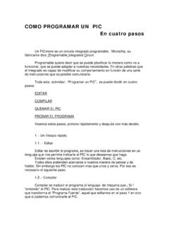
3 If you need to install the device in a place with little signal, you may consider using an external antenna that we may supply as an option to be purchased separately with 50cm cable. You should then insert the SIM Card of the operator you want to use with the right direction according to the following pictures. !Note! : You must remove the PIN request from the SIM before inserting it in the unit, otherwise the device will not work. In order to do so, insert the SIM in a phone and disable the PIN request (usually there is a security menu that enables you to do so). WAFER GSM-RELAY PROGRAMMING You can program the GSM-RELAY with SMS commands using your phone. It is safe to do so because in addition to the fact that other people may not know the number of the SIM inserted in it, we also use a Password that makes it impossible for anybody who doesn't know it to access the system by chance.
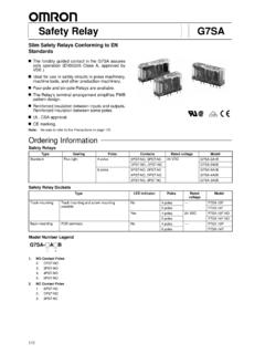
4 Remember that commands must be CAPITAL LETTERS. It is PWD not pwd, CAP not Cap etc. Don't add spaces or any other character. Some complicated Instructions,that cann t be programmed by the phone SMS. That would need to use the PC software to program and inquiry the status of the terminal. The below wire picture is to show how to connect the cable to the PC program connector with the Program connect it in the right direction with the picture. back the SIM door and lift it up the SIM Card into the SIM door making sure that the clipped corner of the SIM card lines up with the clipped corner of the SIM holder the SIM door the SIM door to lock the SIM card in place WAFER GSM-RELAY REMOTE CONTROL UNIT The following compand is used in the GSM-RELAY : #PWD: Password #CAP: Change password #WHL: White List (add or remove numbers) #GOT: Relay working output delay time #MODE: Relay mode #CSQ: Check Signal Quality #SCA: Set service center address #STATUS.
5 Check status Once you issue a command with an SMS, you will receive a confirmation SMS with OK if everything is correct or Err if there is an Error. GSM-RELAY SMS COMMAND LIST: #PWD Password. This command must always come first 6 digits as a password. The standard default one, when the device comes from the factory, is 123456. We suggest that you change it, using the #CAP command. In all the following examples we will use 123456 as an example of password. #CAP Change Password. Use this command to change the password with a new one that you will chose for your device ( don't forget it or you will have to send the unit back to us to reset it, and this has a cost ) The #CAP command must be issued 2 times to be sure you don't digit a wrong one.
6 OF course it must be preceded by the old password. For example, to change the password 123456 into the new password 333444 you need to send the following SMS: #PWD123456#CAP333444#CAP333444 Acknowledge SMS: PWD SETUP OK If you wrote correctly, or an Error message if you made a mistake. If the old password is error,then conformation would be : Error Old Password If you input two different new password,then reply would be : Error New Password,Please Check the input again #WHL White List. This is the command that you will use most. it is used to add or remove numbers that are enabled to control the relay sets into the White List. You can add up to 200 numbers in the list. Every position must be indicated in the command and we advise you to keep a list written somewhere to know which numbers are in and in which position.
7 To add a number, the syntax of the command is the following: #PWD123456#WHL01=61143815 WAFER GSM-RELAY REMOTE CONTROL UNIT Acknowledge would be : WHL01 SET TO 61143815 OK Where 01 is the position in the list and 61143815 is the number enabled. Please note that it is possible to program up to a maximum of 18 digits for a number. If it has more digits you should use the rightmost ones. For example, if your number is 33446665555 you should program 3446665555. If your number appears as +85261143815 you should not program the country code (+852). If your number has only 17 digits or less, it is not a problem. The important thing is that you don't exceed 18 digits. To check which is the number in a place of the list: #PWD123456#WHL01? Acknowledge : WHL01 IS 61143815 OK To erase a number: #PWD123456#WHL01=0000000 (or you can write over it another number you wish to add) Acknowledge : WHL01 SET TO 00000000 List All numbers in the List #PWD123456#WHL=ALL?
8 (PC) Acknowledge : WHL01 IS XXX WHL03 IS XXX WHL08 IS XXX .. #GOT Relay working output delay time. This command is useful in case you need to keep the Relay output working longer. The standard time is 0,3 seconds (300 ms). You can change it with the GOT command. The syntax of the command is the following: #PWD123456#GOT500 (PC$PHONE)(Only for Relay) Acknowledge: DELAY TIME SET TO 0500MS With the above command the delay time has been set to 500 ms (0,5 seconds). You can check what the current relay output delay time is with the command #PWD123456#GOT? (PC$PHONE) (Only for Relay) Acknowledge: DELAY TIME IS 0500 MS Also you can change the Timer Ratio from millisecond to Second or Minute #PWD123456#TIMER-DELAY-AT-MILLISECOND; #PWD123456#TIMER-DELAY-AT-SECOND; #PWD123456#TIMER-DELAY-AT-MINUTE; #MODE Relay Operation Mode SETUP (PC$PHONE) (Only for Relay) #PWD123456#MODE0 Acknowledge: RELAY SET TO MODE0 #PWD123456#MODE1 Acknowledge: RELAY SET TO MODE1 WAFER GSM-RELAY REMOTE CONTROL UNIT If setup to MODE0,that is Momentary pulse mode, when you call the SIM card number , device will toggle the relay and delay a GOT timer ,then the relay will back the previous status.
9 If setup to MODE1,that is Ratchet relay mode,when you call the SIM card number,device will switch to the other status ON or OFF ,and when you call again ,it will switch the status again. #PWD123456#MODE? (Check the RELAY MODE Status) Acknowledge: RELAY IS MODE0 or RELAY IS MODE1 #OUT Relay output control (1)ON the relay output contact #PWD123456#OUTX=ON (PC$PHONE) Where X is the number of the relay in the list (X is from 1 to 7) Acknowledge: OUTX ON OK (2)OFF the relay output contact #PWD123456#OUTX=OFF (PC$PHONE) Where X is the number of the relay in the list (X is from 1 to 7) Acknowledge: OUTX OFF OK (3)ALL the relay control at the same time #PWD123456#OUT=1101011 (PC$PHONE) Where the number is 1 or 0 to ON or OFF the relay.
10 Acknowledge: #PWD123456#OUT=1101011 OK (3)Check the relay status #PWD123456#OUT? (PC$PHONE) Check the status of all the relay Acknowledge: OUT 1110000 (the Number 1 means RELAY ON and 0 means RELAY OFF) RELAY Status when power on #PWD123456#POWER-RESET ;Relay status would be reset to OFF,when power On again #PWD123456#POWER-SAVE ;Relay status would be saved when power off #CSQ Check GSM signal quality. (PC$PHONE) This command is useful to see what is the GSM network signal level your GSM-RELAY is receiving. It ranges from 0 to 32 (if it is 0 we doubt it will ever ). You should have a signal above 12 to be sure of being able to control the relay sets in any condition. Better if above 16. You should add an external antenna if this is not the case, or eventually even change operator with another that serves your area better.