Transcription of Guidance Note Shear connectors No. 2 - Steel Construction
1 Guidance Note Shear connectors No. Scope of connectors to provide just sufficient Shear This Guidance Note gives advice on the resistance for economy. Hence, Shear flows Shear connection between the Steel girder should be calculated at supports, at midspan, and concrete slab of a typical Steel composite and at least one position in between, bridge. Various means of providing the Shear quarter points, in order to plot a Shear flow connection are mentioned, but this note profile along a girder. There may also be a focuses on the use of Shear studs, which are need to calculate Shear flow at a significant predominantly used. EN 1994-2 only gives change in beam section. specific design rules for Shear studs, but other connectors may be designed in accord- ance with the other Eurocode rules. The National Annex to BS EN 1994-2 gives some design rules for block and hoop connectors . This brief note is intended to outline the design issues to consider, guide the reader to the appropriate code clauses, and discuss some fabrication aspects.
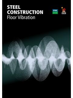
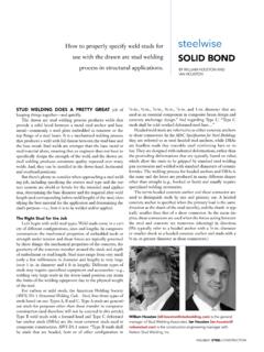
2 General Shear connectors are required on the top flange of Steel composite bridge girders to provide the necessary Shear transfer between the Steel girder and composite slab that is required for composite action. The most Figure 2 Block and hoop, and channel Shear widely used form of Shear connector is the connectors headed stud, or Shear stud. Refer to Figure 1. Static design The Shear connection needs to be verified at ULS and at SLS. The requirement at SLS is given in Clause (3) of EN 1994-2 as a limit to the maximum force under the charac- teristic combination of actions. The SLS limit will usually only be critical for long span bridges with a high dead load component. Figure 1 Typical Shear stud connectors The advantages of Shear studs over other For Class 1 or 2 sections, because the bend- forms of connectors are that the welding ing resistance at ULS is calculated in terms of process is quick and simple, they provide little a plastic stress distribution, Shear flow in obstruction to the slab reinforcement, permit zones where the slab is in compression must more satisfactory compaction of the concrete also be calculated using a plastic stress around the connectors , and provide equal distribution.
3 In zones where the slab is in Shear strength in all directions. tension, the Shear flow may be calculated on the basis of elastic section properties and Other forms of Shear connector, which are assuming the concrete to be uncracked. The sometimes used include block and hoop, and unconservative neglect of plasticity is offset channel connectors , as illustrated in Figure 2. by the conservatism of ignoring cracking. These types of connector are typically used where large Shear transfers are required, as The design resistance of Shear connectors is an alternative to closely spaced Shear studs. given by Clause of EN 1994-2-2. For elastically designed zones, the spacing of the Shear connectors must be designed to pro- connectors may provide a stepped' re- vide static strength, and for fatigue loading. sistance, subject to the provision of sufficient The Shear flow varies along the length of a total resistance over each length. The maxi- girder, being highest near the supports, and it mum calculated Shear flow within the length is customary to vary the number and spacing of any such group must not be more than SCI P185 Guidance notes on best practice in Steel bridge Construction GN211R2 Revison 2.
4 Guidance Note No. 10% in excess of its design resistance per be expected, due to the higher currents and unit length. For plastically designed zones, magnetic field effects. this provision does not apply as the connect- ors must be proportioned to resist the aver- Table 1 Standard sizes of Shear Studs age force in the inelastic zone. Stud Stud diameter (mm). height 16 19 22 25. Fatigue design (mm). Verification of the connectors for fatigue is 125. carried out for an equivalent constant range 150. of Shear stress given by Clause of 175. EN 1994-2, based on the stress range due to 200. the fatigue load model 3 (FLM3) and damage 250. equivalence factors. The fatigue strength Commonly used in bridges curve is that for detail category 90. Adequacy Occasionally used in bridges is assessed to Clause ; for connectors Available but rarely used in bridges on tension flanges interaction with the tensile stress in the flange needs to be considered EN 1090-2 refers to EN ISO 13918 for the but does not normally govern, since worst requirements for stud Shear connectors .
5 In Shear and worst tension rarely coexist. that Standard, two grades of carbon Steel Fatigue may govern the spacing of connect- stud are given, SD1 and SD2. Grade SD1 has ors in midspan regions of longitudinal mem- the higher strength (minimum yield strength bers but does not often govern near supports. of 350 N/mm2, and a minimum tensile strength of 450 N/mm2 but these values are Transverse reinforcement less than those for studs previously supplied Transverse reinforcement is required in the to BS 5400-5. It is suggested that SD1 studs slab to provide Shear resistance. This is be specified but with minimum yield strength needed both to prevent splitting of the con- of 385 N/mm2, and minimum tensile strength crete adjacent to the stud and to allow load to of 495 N/mm2, which is the strength that has spread out across the width of the slab. Refer been available in the UK for very many years. to EN 1994-2, Clauses and An interaction between Steel requirements for Shear studs are generally attached to the top bending in the slab and longitudinal Shear flanges of girders using a stud welding gun.)
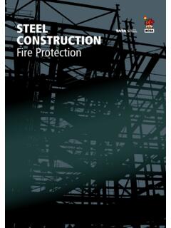
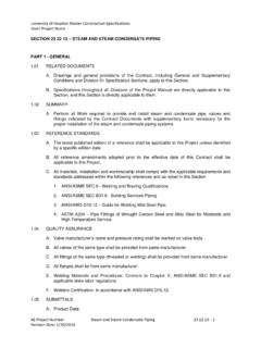
6 Has to be considered. Particular care is The stud is held in the welding gun and an needed for ladder deck Construction where arc is struck between the stud and the flange the transverse reinforcement required for plate. The arc melts a portion of both the stud bending is usually smaller, and may not be and the plate in a set time. The gun then sufficient on its own to transfer high Shear automatically plunges the stud into the molten flows. Additionally, cross girders in ladder pool of metal and holds it there until the weld decks may have their transverse reinforce- solidifies. The molten metal is held in place ment in tension from the global behaviour of by a ceramic ferrule, which also serves to the main beams. In such cases, the effect of shield the arc. Figure 3 illustrates a stud with this tension must be fully added to that from the ceramic ferrule still in place. longitudinal Shear see Hendy and Johnson (Ref 4) or P356 (Ref 5). Testing shows that the weld collar so formed is very important in transmitting Shear .
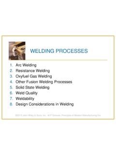
7 The Practical aspects resistances for Shear studs in EN 1994-2. Standard sizes for Shear studs, which are therefore only apply to studs attached in this readily available from suppliers and typically way. Studs attached by friction welding, for used in Steel composite bridge decks, are example, cannot be designed using the indicated in Table 1. Stud heights outside this EN 1994-2 rules for static or fatigue strength. range are available, and stud manufacturers should be contacted to check availability. Although studs over 19 mm diameter are available, they are not preferred by fabrica- tors, as a higher level of defective welds can 2015 The Steel Construction Institute GN211R2 Printed 01/10/15. Guidance Note No. be provided. This leads to a recommended minimum edge distance of 100 mm where permanent formwork is used, comprising a 25 mm return of the paint into the in-situ concrete/steelwork contact area, a 25 mm tolerance on girder seating and formwork length and a 50 mm seating length.
8 In other cases, a minimum of 50 mm will generally be sufficient. The minimum spacing between the centre- lines of Shear studs is governed by access requirements for the stud welding gun. A. minimum spacing of between 60 mm and Figure 3 Typical Shear stud after welding 70 mm is possible, depending on the size of the studs, but a minimum of 100 mm is pre- Shear studs should be welded in accordance ferred by fabricators. with the manufacturer's instructions, including preheating where necessary. The studs, and The maximum longitudinal spacing is defined plate to which they are welded, must be dry in EN 1994-2, Clause (3), and is the and clean otherwise the quality of the weld lower of the following: will be adversely affected, and welding should not be carried out when the temperature is 800 mm below 0 C. 4 x concrete slab thickness A lower value if needed to restrain local The equipment required for stud welding is buckling of the flange such that it achieves specialist but readily portable, so although the a classification of Class 1 or 2.
9 Majority of studs are welded in the shop, they could be welded on site if required, although There are also further limits in EN 1994-2 Ta- it is unlikely to be economic for small num- ble on the spacing of studs on composite bers of studs: fillet welding is more practical plates, such as in composite box girders, where it for small numbers and such welds are struc- is necessary for the studs and concrete to restrain turally satisfactory. Where studs are manually the flange. welded on site, there should be a defined weld procedure; it is likely that preheat will be In determining the actual spacing of Shear needed because the weld is small in extent. studs along the length of the Steel girder it is usual to adopt a spacing equal to the trans- Spacing of Shear connectors verse deck reinforcement spacing, or multi- The minimum distance between the edge of a ples thereof. This facilitates the easy fixing of Shear connector and the edge of a flange the deck reinforcement.
10 Plate is specified as 25 mm in EN 1994-2, Clause (2). However, other issues Note that in Steel box girders with composite need to be considered as follows. flanges, there will be a concentration of Shear transference local to the box webs. Shear Many Steel composite decks are constructed studs will need to be arranged to suit this, using permanent formwork, usually either resulting in a higher density of connectors precast concrete Omnia' planks or GRP above the webs - see EN 1994-2 Clause panels. Allowance needs to be made for the bearing or seating lengths required, which are Size of Shear connectors typically 50 mm, and also tolerances on the Clearly, the design for Shear transfer will have girder spacing. The extent of the painting a bearing on the size of the Shear stud. How- envelope is also important, as Shear connect- ever, EN 1994-2 defines other criteria to ors should ideally not be painted but a mini- consider: mum bond length for the paint of 25 mm beyond the end of the precast element should SCI P185 Guidance notes on best practice in Steel bridge Construction GN211R2 Revision 2.