Transcription of Guide to Industrial Fiber Optics - Relcom Inc
1 Guide to Industrial Fiber Optics All rights reserved. No part of this manual may be reproduced, photocopied, stored on a retrieval system or transmitted without the express prior consent of Relcom , Inc. 2001. Guide to Industrial Fiber Optics Guide to Industrial Fiber Optics Benefits and Drawbacks of Fiber Optics .. 2. Fiber Optic Technology and Terminology .. 4. Relcom , Inc. Signal Measurement .. 5. 2221 Yew Street Fiber Optic Cable Characteristics .. 6. Forest Grove, OR 97116. USA Detector Characteristics .. 10. (503) 357 5607 tel Emitter Characteristics .. 11. (503) 357 0491 fax Signal Budget .. 12. (800) 382 3765 Connectors .. 13. Splices .. 14. Copyright 2001 Relcom Inc. Testing .. 15. All rights reserved. Network Topologies .. 15. Guide to Industrial Fiber Optics The purpose of this Guide is to provide the Industrial user enough informa- tion about Fiber Optics to install and successfully use the Carrier-band Fiber Optic Repeater.
2 Fiber optic technology has caught the imagination of many people. The ability to shine a light through a small glass Fiber over considerable distances has been utilized for diverse applications. Long distance telephone lines use Fiber Optics . Signals for many conversations can be carried over a single Fiber without amplifiers. An anti-tank missile uses Fiber optic cable for flight control. Signals on Fiber optic cables cannot be jammed. Medical equipment uses Fiber Optics to illuminate and observe inside the body and in some cases to send high-energy laser pulses through the Fiber to per- form internal surgery. An intrusion alarm system uses Fiber optic cable as the sensing element. The largest volume of Fiber Optics cable has been used for telephony. As most of the long distance telephone trunks were completed, an over-capacity of Fiber optic cable manufacturing resulted.
3 This sent Fiber optic cable sales people out in search of new applications. Every so often, proposals are made to bring Fiber optic cables to the home for both telephony and cable television use. Technically this is fea- sible, but economically it makes little sense. Current copper cable technology is adequate and is already in place. This is but one area where Fiber optic technology has been oversold. A relatively new area where Fiber Optics is being touted is Local Area Networks, LANs. Fiber Optics is said to have a very high data carrying capacity and low cost. Both parts of this statement are true. High quality glass Fiber optic cable can carry a large amount of data and plastic Fiber optic cable is inexpensive. Unfortunately, this is not one and the same cable. Many other aspects of Fiber optic technology have been similarly oversold for LANs.
4 This Guide provides information so that facts and fiction about Fiber Optics can be separated and that the true benefits of Fiber optic communications can be utilized effectively for Industrial applications. The Repeater is used as the example in this Guide and examples about Fiber Optics are general. At this writing, Fiber optic technology is advancing rapidly. There may be Fiber optic products or laboratory test results that are different than the examples given. This Guide does not address the many other aspects of Fiber Optics that may be interesting to design engineers or researchers. 5 Mbit/s Carrier band Fiber Optic Repeater 1. Models CBR 2 and CBR 3. For further reading, an excellent book, Technician's Guide to Fiber Optics , #82118, is available from: AMP. Harrisburg, PA 17105. USA. Tel: 717-564-0100. Benefits and Drawbacks of Fiber Optics Fiber optic technology has a number of benefits for Industrial communications: Long Distance Signals can be sent over Fiber optic cable for long distances.
5 For example 9 km without the need for intermediate amplifiers. Ground Isolation Since electrical currents do not flow on Fiber optic cables, differences in ground potentials between end points do not affect signal transmission. Ground isolation is useful in power plants and switching yards where the differences in ground potentials are high. Grounding systems are not needed for Fiber Optics . Lightning Protection Because Fiber optic cables do not conduct electricity, signals are not affected by lightning. Cable Routing Since Fiber optic cables do not conduct electricity, they can be placed on the same cable trays as power carrying cables. Noise Immunity Fiber optic cables are immune to electromagnetic noise from radio stations, motor turn-on surges, welding discharges, electrostatic discharges, florescent lights, typewriters, and other Radio Frequency Interference, RFI.
6 NOTE: Although Fiber optic cable is not susceptible to RFI, that does not mean that Fiber optic data communications are error free. As will be explained later, a Fiber optic communications system as a whole has error rates comparable to quality copper cable-based communications systems. Intrinsic safety In places such as chemical plants and grain silos, the atmo- sphere is often potentially explosive. Great care has to be taken with electrical wiring and data communications wiring to insure that sparks will not ignite the atmosphere. Signals on Fiber optic cable will not cause sparking and are intrinsically safe. 2 5 Mbit/s Carrier band Fiber Optic Repeater Models CBR 2 and CBR 3. Small size Fiber optic cables are relatively small. Where cable has to be added to conduits that are already partially filled with existing cables, the small size cable can be advantageous.
7 There are other benefits to using Fiber Optics , but generally these are not relevant for Industrial applications: High data carrying capacity Fiber Optics cables are able to carry high data rates; for example, 300 Mbits/second. In most Industrial applications, however, data is transmitted at 1 to 10 Mbits/second. For these moderate data rates, there is no need for the high data rate capability. Security Unlike copper cables, Fiber optic cables are difficult to tap and to extract part of the signal without disrupting the operation of the Fiber optic communications system. Also, Fiber optic cables do not radiate electromag- netic signals that can be picked up with sensitive antennas. For these reasons, it is difficult for unauthorized parties to eavesdrop on Fiber optic networks. Generally, security from eavesdropping is not a requirement of Industrial communications.
8 If there were only advantages to Fiber Optics , it would be used universally. Fiber Optics is not used everywhere because it also has disadvantages: Costly The Fiber optic cable and the electronics in the equipment attached to Fiber optic cables are more expensive than comparable copper cable-based communications systems. Moreover, two fibers are needed rather than just one to have two-way communications. The connectors and the equipment needed to install them is more costly than for copper cable. Signal Distribution In copper communications systems, many devices can share the same cable and communicate with each other. In Fiber Optics this is not practical. Signal transmissions and reception are point-to-point. A central signal distribution device is necessary to interconnect more than two stations. More Training Technicians working with Fiber optic equipment need more training than copper cable installers.
9 More Care Fiber Optics is very susceptible to mishandling and dirt. Workers dealing with Fiber Optics have to use extreme care not to damage or degrade the performance of the Fiber optic communications system. 5 Mbit/s Carrier band Fiber Optic Repeater 3. Models CBR 2 and CBR 3. Fiber Optic Technology and Terminology A Fiber optic communications system is composed of three types of parts: the Transmitter, the Fiber Medium (cable) and the Receiver. The transmitters and receivers are located inside the computers, robots, controllers, or other devices that need to send or receive data. These end devices are called Stations. The Repeater is a station. Signals are transmitted over a Fiber optic cable in only one direction. This is called Simplex communication. Generally, two-way communi- cation is needed between stations so that two of each of the basic components are needed.
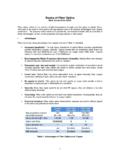
10 The two-way communication is called Duplex. The Repeater re- quires duplex communications. The transmitter is made up of a light emitter and the electronics that modulate the light to send information. The emitter is generally a Light Emitting Diode, LED. The medium is the Fiber optic cable and the associated connectors, splices. etc. that carry the light from the transmitter to the receiver. The receiver is a light detector, that turns the received light signals back to electrical signals and an amplifier that conditions the signal for use in the station. The detector is a light detecting diode. Figure 1 | Fiber optic system components 4 5 Mbit/s Carrier band Fiber Optic Repeater Models CBR 2 and CBR 3. Signal Measurement The strength of the optical signal is measured in two types of units: micro- Watts, W; and dBm. These two measurements are related by the equation: signal W.


