Transcription of GUIDELINES FOR EMBANKMENT CONSTRUCTION
1 GUIDELINES FOR EMBANKMENT CONSTRUCTION GEOTECHNICAL ENGINEERING MANUAL GEM-12 Revision #4 AUGUST 2015 EB 15-025 Page 1 of 30 GEOTECHNICAL ENGINEERING MANUAL: GUIDELINES FOR EMBANKMENT CONSTRUCTION GEM-12 Revision #4 STATE OF NEW YORK DEPARTMENT OF TRANSPORTATION GEOTECHNICAL ENGINEERING BUREAU AUGUST 2015 EB 15-025 Page 2 of 30 TABLE OF CONTENTS 1. 2. EMBANKMENT FOUNDATION ..4 Stable Foundation ..4 Transitional Foundation ..4 Unstable Foundation ..5 Unsuitable Foundation ..6 3. EMBANKMENT ..7 Pneumatic Tired Roller ..7 Vibratory Drum Compactor ..8 Sheepsfoot Roller ..9 Smooth Steel-Wheel Roller ..10 Other Rollers ..11 4. compaction control ..13 Moisture - Density - Strength Relationship ..13 5. PROOF ROLLING ..18 6. EMBANKMENT FAILURE ..19 7. WINTER EARTHWORK ..20 Winter Earthwork Inspection ..21 8. SUMMARY ..22 9. ADDITIONAL FIGURES.
2 23 APPENDIX ..30 A. Winter Earthwork Submittal .. A-1 B. Unsuitable Material Treatment - Design and CONSTRUCTION .. B-1 EB 15-025 Page 3 of 30 1. INTRODUCTION The specifications, plans, and Standard Sheets state the requirements of EMBANKMENT CONSTRUCTION in precise terms. This guide is intended to describe less technically and hopefully, more understandably; how to construct an EMBANKMENT . The guide discusses, EMBANKMENT Foundation EMBANKMENT compaction control Moisture Density Strength Relationship Proof Rolling EMBANKMENT Failure Winter Earthwork Reference is made throughout the guide to the Standard Specifications, Standard Sheets, plans, proposals and various procedure manuals. It is intended that the guide will stimulate the reader to study these sources. Figure 1 Definition of EMBANKMENT CONSTRUCTION Terms EB 15-025 Page 4 of 30 2. EMBANKMENT FOUNDATION The EMBANKMENT foundation is the ground surface upon which the EMBANKMENT is placed.
3 It may be: Stable Transitional (part cut, part fill) Unstable Unsuitable Stable Foundation Fortunately, most EMBANKMENT foundations are stable. If the EMBANKMENT is to be less than 6 ft. ( m), including the thickness of the subgrade and pavement, the specifications require that the topsoil be removed. There are situations where, although the EMBANKMENT is less than 6 ft. ( m) high, it would be advantageous to leave the topsoil in place such as where the topsoil is thing or removal would disturb and weaken the underlying soils. The plans or proposal will indicate if the topsoil is to be left in place. Transitional Foundation The longitudinal transition EMBANKMENT foundation condition is encountered where the alignment places the EMBANKMENT alongside a hillside or where an existing EMBANKMENT is to be widened. The newly placed fill tends to slide down the slope of the hillside or the existing EMBANKMENT .
4 The standard sheet entitled Earthwork Transitions and Benching Details (available at the following website: ) describes the preferred treatment for this condition. In effect, steps or benches are built into the existing slope to reduce the tendency of the new EMBANKMENT to slide down the existing hillside or slope (Figures 2, 18 & 19). Figure 2 Benching EB 15-025 Page 5 of 30 The same Standard Sheet ( Earthwork Transitions and Benching Details ) describes the proper treatment of the transverse transitional EMBANKMENT foundation at the interface where the roadway changes from EMBANKMENT to cut. When an EMBANKMENT is placed against existing ground, such as occurs in a fill-cut situation, a bump may occur in the pavement at the interface. This occurs because the existing hillside is inherently different than the constructed EMBANKMENT . The standard treatment provides a more gradual transition between the fill and the cut.
5 Figure 3 Gradual Transition Between Cut and Fill Unstable Foundation Unstable EMBANKMENT foundation soils are usually silts and/or clays that are influenced by water. The saturated soils are too weak to withstand the high contact pressures of earthwork CONSTRUCTION equipment. The strength or stability of the soil may be increased by lowering the water table and the degree of saturation of the soil . In some cases this may be accomplished by installing ditches, either permanent or temporary, prior to CONSTRUCTION . The high contact pressures caused by CONSTRUCTION operations on an unstable soil may be reduced by limiting the size of the CONSTRUCTION equipment being used until the EMBANKMENT is high enough to distribute the load of heavier equipment. This pressure may also be reduced by the CONSTRUCTION of a working platform as described in the Standard Specification EMBANKMENT Foundation.
6 This working platform is usually constructed by end EB 15-025 Page 6 of 30 dumping and bulldozing EMBANKMENT or granular material to a maximum thickness of 3 ft. ( m) (Figures 20 & 21). The working platform distributes the load of the equipment, thereby reducing the contact pressure on the unstable material. The CONSTRUCTION of such a working platform requires the permission of the Engineer. Geotextile (filter fabric) placed on the unstable foundation and under the working platform may also be effective as a separating membrane to help support the high CONSTRUCTION loads. The Regional Geotechnical Engineer should be consulted for recommendations of the most appropriate method of treating an unstable EMBANKMENT foundation. Unsuitable Foundation The typical unsuitable EMBANKMENT foundation is a wetland. Unsuitable material is organic, usually wet, black, and extremely weak (Figures 21 & 22).
7 It is incapable of supporting any significant load. Improperly treated unsuitable materials will settle for many, many years. The unsuitable material is usually removed and replaced with suitable material before the EMBANKMENT is constructed. The Standard Sheet entitled CONSTRUCTION Details Unsuitable Material Excavation and Backfill (available at the following website: ) shows the details of the EMBANKMENT foundation treatment for most unsuitable material deposits. The plans should indicate the areas of unsuitable material, the depth of the material that must be removed and any required special treatments. If, during CONSTRUCTION , unsuitable material is encountered unexpectedly, work in the area must be suspended until the Regional Geotechnical Engineer has determined the extent of the deposit and how it should be treated. An additional useful source of information on the treatment of unsuitable EMBANKMENT foundation areas can be found in the treatise entitled Unsuitable Material Treatment Design and CONSTRUCTION dated October, 1986.
8 A reprint of this treatise is provided in Appendix B. EB 15-025 Page 7 of 30 3. EMBANKMENT The EMBANKMENT consists of a series of compacted layers or lifts of suitable material placed on top of each other until the level of the subgrade surface is reached. The subgrade surface is the top of the EMBANKMENT and the surface upon which the subbase is placed. Any suitable material (see ) may be used to construct an EMBANKMENT , although the Contractor may have to manipulate this material to make it stable. The maximum dimension of any particle of the material may not be greater than the loose lift thickness. Any particles that are larger than the loose lift thickness must be removed and disposed of, or may be put in the EMBANKMENT side slope (see ). The components of EMBANKMENT CONSTRUCTION are: Lift Thickness Material Degree of compaction The thickness of the lift is limited by the type and size of compaction equipment the contractor chooses to use.
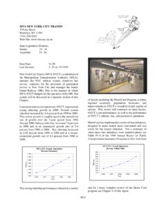
9 The Standard Specifications indicate the maximum loose lift thickness and mechanical requirement for various types of compaction equipment such as pneumatic-tired rollers, vibratory drum compactors, segmented pad rollers, and smooth steel wheel rollers (see ). The compactors must have attached to them an identification plate which includes the manufacturer s name and the model number of the equipment. Manufacturer s brochures should provide the necessary data to determine the qualifications of the compactor. Pneumatic Tired Roller The pneumatic tired roller is classified according to tire size, tire pressure and wheel loads. Charts (Figures 203-1 & 203-2) in the Standard Specifications relate these classes to maximum loose lift thickness. The roller must make at least 6 passes at defined speeds. Figure 4 Pneumatic Tired Roller EB 15-025 Page 8 of 30 Vibratory Drum Compactor The classification of a vibratory drum compactor is more complex, requiring computations based upon unsprung drum weight, drum width, dynamic force, operating frequency and rating frequency.
10 This data must be supplied by the manufacturer. Fortunately, most of the vibratory rollers have been pre-qualified. The Geotechnical Engineering Bureau s website includes listing of rollers, by manufacturer and model, and the information needed to determine the maximum loose lift thickness, speed, number of passes and vibration frequency ( :7779/pls/portal/docs/PAGE/WCC_PG/TSD/TS D_BUREAUS_TAB/TSD_GEOTECHNICAL_ENGINEERI NG_BUREAU_ ) This listing is updated periodically. However, if an unlisted model is to be used, it may be evaluated by the Engineer based on the Manufacture s equipment specifications. The simplest way to make the evaluation is to supply the Regional Geotechnical Engineer with the data from the identification plate. The Geotechnical Engineering Bureau will acquire the equipment specifications and respond with the necessary information. Figure 5 Vibratory Drum Compactor EB 15-025 Page 9 of 30 Sheepsfoot Rollers Sheepsfoot rollers have largely been replaced by its more efficient variant, the segmented pad roller, and will only rarely be encountered.