Transcription of GUIDELINES FOR INSTALLING FLEXIBLE DUCT
1 A. CODE REFERENCE1. The au thority havingjurisdiction shouldbe referencedto det erminewha t la w,or din an ce or codeshallappl y in the use of FLEXIBLE Air duct s and Air Connector s. 2. Air Duc ts, id en tif ie d by a re ctangularshapelistingma rk, have no inst all edlengt h li mi ta tio n. Ai r Co nnector s, identifiedby a roundsh apelistingma rk,sha ll not be inst al led in lengths greaterthan14 GENERAL1. The rou ti ng and len gth of fl ex ible duc t, the numberof de gree s of each be ndand the amo un t of sagallowed betw eensup portjoin ts will have se riou seffe cts on syst em pe rfo rmancedue to the increasedresistance each intr e the min imu m length of flexibleductto makecon nec tio ns. It is notre commen ded tha t exces s le ng ths of ductsbe in stalledto allowfor possiblefu tu re rel oca ti ons of air te rminal Thisprodu ct is for in dooruse not installproductwhe re exposureto dire ct sun lig ht ca n oc cu r.
2 Pro longedexposure to sunlightma y ca us e de gra -dation of vap or bar rie ner co re may degradeif th e ductis positionednear a bio -tr eatmentlamp (UV emi tt er) in sta lle d wi th in the HVAC system4. Ter mi nal devi ces shall be su pp ortedindependently of the fl exibleduct .5. Re pai r to rn or da maged vapor ba rr ier/jacke t withdu ct ta pe liste d andlabele d to St anda rd UL internal core is penetrated,replace fl exib leduct or trea t as a co nn ec tion .C. INSTALLATION1. Ins tal l du ct ful ly ex tend ed, do not in stallin the compressedsta te or useexc es s leng ths . Th is will not ic ea bly Avo id ben din g du cts ac ros s sharpcornersor incidental conta ct with metalfi xtu res, pi pes or con duit s.
3 Rad ius at centerline shallnot be les s than oneduct di ame te Do not ins tal l nea r hoteq uipment( ,furnaces,boilers, steampi pes,etc .) tha t is abo ve the rec ommen ded fle xibledu ct use te mp CONNECTING,JOINING AND SPLICING FLEXIBLE DUCT1. All co nnections,joint s and splicesshallbe madein accordancewit h the man u-fact ure r s inst allationinst ruct All ta pes,mastics, and non-metallic fasteners(plast ic clamps)usedfor fieldinst alla ti on of flexibleduct s sha ll be listedand labeledto St andard UL 181B Closur e Systemsfor use with FlexibleAir Ductsand Air Con nect ors. Non- metallicfast en er s are li mi ted to 6 inch maximumposit ive pr Sh eet metalcollarsto whi ch th e fl ex ibl e du ct s ar e atta che d sha ll be a mi ni mumof twoinch es in lengthand shall be be ade She et metalsleevesusedfor joiningtwo sectionsof flexibleduct shallbe a min -imu m of 4 inchesin leng th and shallbe beadedon SUPPORTINGFLEXIBLE DUCT1.
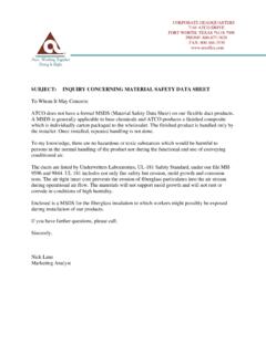
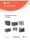
4 Flexib le duct shallbe supported at manufacturer s recommendedinter vals,butat no gr eaterdistancethan four feet. Maximumpermissib le sag is 1/2 inch per footof rigid ductingor equipmentshallbe considered a support izontalduct runswith shar p bendssha ll ha ve additional supports beforeand afterthe bendappr oximatelyone duct diam eter distancefr om the centerlineof the Hangeror saddlemater ial in contactwith the flexibleduct shallbe of sufficientwidth to pr eventany restr ictionof the inter nal diam eter of the ductwhentheweightof supportedsectionrests on the hanger or saddlemater ial. In no casewill the mater ial contactingthe flexibleductbe less than1- 1/2 inch Flexi ble ducts may res t on ce ili ng jo ists or tr uss supports.
5 A ma ximumspa c-ing betw een sup por ts shal l no t ex cee d th e maximum spa ci ng per manuf actur-er s ins tal la tion in stru ctio Sup por t the ductbe twe en a met al co nnecti on and a be nd by allowing theduct to exte nd st rai ght fo r a few in che s befo re making the be nd. This will avoidposs ible da mageof th e fl exi ble du ct by the edg e of the sh ee t metal 1/2" 1/2" " " Verti call y ins talledductsh all be stabi lized by sup port str aps at a maximumof 6 fee t on : Fa ctor y- made air ductsmay not be use d for ve rticalrise rs in air ductsy stem s se rv ing mor e tha n tw o INSTALLATIONRESTRICTIONSAND USE LIMITATIONSTher e ar e specificrestrictionsand lim itationsrelatedto the use of FLEXIBLE e ar e due to NF PA Standards,modelcodesand var s ar e due to end use per form ancewher e the pr oductwas not designedforthat specificuse.
6 Som e, but not all inclusive,ar e as usedfor verticalrisersser ving mor e thantwo stor ies inheightwhenconformanceto NFPA90A or 90B is requir usedin systems with enteringair tem perature higherthan250 F[121 C] be installedin accordancewith conditionsof a fire- ratedfloor /r oof ceilingassembly, ductsshallconformwith the designof the testedfir e-r inter ruptedat the im mediateareaof operationof electric, fossilfuel or solarener gy collectionheatsour ces to meet connectors (doesnot applyto air ducts)shallnot be installedin lengthsgr eaterthan14 feet [ m] for any giv en run; shallnot passthr oughanywall,partitionor enclosure of a verticalshaftwith a 1 houror mor e fir eresistiverating.
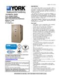
7 Shallnot passthr oughfloor penetratewallswher e fir e dampers ar e requir be usedoutdoors unlessspecificallydesignedto withstandexposure to dir ect sunlightand the weathering elem be usedto vent appliancesfor cooking,heatingand clothesdrying unlessappr ovedand recommendedby the be installedin concrete, bur ied belowgradeor in contactwiththe gr JOISTSCEILING JOISTS6'6' ALLA TIO N IN STRU CTION SNo nmet al lic Air duct s & Air Co nn ecto rs wi th Pl ain En dsUL 18 1 Lis ted Un der Fi le MH95 96 , 98 44 APPL ICA TI ON:Ai r du cts and ai r co nne ct ors maybe conne ct ed to any ro und shee t metal fit ting (collar, pipe co uplin g, etc.) orsplic ed to any other du ct of a cor resp ond in g nomi nal si ze.
8 PRO CED URE:1. Fo llow detai led ins tr uc ti on s on righ t side of pag e for mak ing con nec ti on s/splic Sel ec t and use ap pr opr iat e tool s/ma terial s listed bel Fo llow Precaut ion s listed bel ow .4. Refer to instal lation gu idel ines on re ver se side of page .TOOLS AN D ACC ESS ORY MAT ER IAL S REQ UI RED:1. Kni fe or Sc issors/Wi re Cutt er: Us e kni fe or sci ss or s to cut du ct wal l. Us e wire cutters to cu t spira l wire he li duct Tap e: Us e onl y ta pes that ha ve been listed and label ed to Stan dar d UL 181B and ma rke d 1 81B -F X .Use two wraps of 1- 1/ 2 inc h mi ni mumwi dt : Whenal um inum foi l tapesare requ ired , us e onl y ta pes that ha ve been li sted and la beledtoSta nda rd UL 18 1A and mar ke d 181 A-P.
9 Us e on e wrap of 2-1 /2 inch min imu m wid Metal Cl amp /S cr ew Dr ive r: Use for low , medi um or hi gh pr es su re sy st em s up to 10 inch .4. Non- Met al lic Mec hani cal Fa stene r (Pl as ti c Clamp) /Fa stene r To ol : Use for low to med iu m pre ssu re systemsup to 6 inc h max imumpo siti ve pre ssur e. No n- Meta lli c Me cha nical Fas te ners are li mited to use withbead ed col lars and fitti ng s. Use onl y no n-meta lli c fas tener s th at havebe en lis ted and la beledto Sta nda rd UL181B an d mar ke d 18 1B- C . Use the ap prop ri ate ti gh te ning tool per the fa stene r ma nu fa ctu re r s instruction Ma sti c: Use mast ic tha t ha s be en listed and label ed to St andard UL 181 Band mark ed 181 B- M on containe r.
10 (Ap ply ma stic app ro ximat el y 2 inc he s wide uni form ly arou nd th e col lar of the meta l fi tting . Sli de at le ast 1 ofcor e over the fitt ing and se cu re wi th clamp .) Re fer enc e data pr ovided on th e masticcon tain er for applica tionand han dl ing inf orm ati AUTIO NS: Do not us e o utdo or s or in st al l where du ct can be ex pose d to direc t su nligh t. Prolo nge d expo su re maycaus e degr ada tion of va por ba rr ier. (does not app ly to 040 Mo bile Hom e duct s) Do not inst al l whe re duct ca n be expo se d to UV radi ati on fr om bi o- tr ea tme nt lamps with in th e HV AC su re may ca us e de gr adat ion of th e inn er co re. Do not ex ceed pu bl ishe d pr es su re or tempera tur e limi ts.