Transcription of Guidelines for the Design and Construction of Stormwater ...
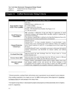
1 Guidelines for the Design and Construction of Stormwater Management Systems Presented by DEP s Bureau of Water and Sewer Operations and Bureau of Environmental Planning and Analysis 2 Presentation Agenda DEP s Stormwater Performance Standard How is the New Rule Different? Stormwater Management Systems Overview Choosing the Right System System Layout and Design System Design Example Inspections and Maintenance Additional Guidance Questions and Discussion 3 DEP s Stormwater Performance Standard Modifies the flow rate of Stormwater to the city s combined sewer system for new and existing development, as part of sewer availability and connection approvals Promulgated on January 4, 2012 as amendment to chapter 31 of Title 15 of RCNY Rule effective date is July 4.
2 2012 4 Purpose and Need Provide additional sewer capacity for the future Provide flexibility for applicants to comply with stricter release requirements Support city s comprehensive approach to reduce CSOs and 2010 NYC green Infrastructure Plan Support a phased approach toward attaining future federal and state Stormwater requirements 5 Amended Rule Language 31-03 Stormwater performance standard for connections to combined sewer system: For a New Development: Stormwater Release Rate will be the greater of cfs or 10% of the Allowable Flow If Allowable Flow is less than cfs, the Stormwater Release Rate shall be the Allowable Flow Allowable Flow is the Stormwater flow from a development that can be released into existing storm or combined sewer based on drainage plan and built sewers For Alterations.
3 Stormwater Release Rate for the altered area will be directly proportional to the ratio of the altered area to the total site area and no new points of discharge are permitted Alterations are as defined in the Construction Codes and related requirements for any horizontal building enlargement or any proposed increase in impervious surfaces 6 Examples: Stormwater Release Rates Examples: A typical one acre site in Brooklyn will be required to detain and release runoff at a rate of cfs under the proposed rule compared to cfs under existing standards For a half acre site in Brooklyn, the allowable flow would be cfs.
4 Since 10% of the allowable flow is cfs, the release rate would be cfs For a 3,000 sq ft site in Brooklyn, the allowable flow would be cfs. Since this is less than cfs, the release rate would be cfs. 7 How is the New Rule Different? Many new release rates are 10% of former allowable flows, as determined by drainage plan and built sewers Increased onsite management of Stormwater runoff through detention and retention Because runoff from smaller sites may not exceed cfs, medium and large lots are more likely to be affected Incentives for green infrastructure.
5 Including recycling and infiltration systems 8 Gravel Bed Systems Void space within gravel used to detain water System can promote infiltration with an open bottom Incorporates pretreatment and outlet control structures Water distributed by manifold and collected by underdrain 9 Perforated Pipe Systems Void space within perforated pipes and surrounding gravel used to detain water Open voids within perforated pipes can reduce footprint System can promote infiltration with an open bottom 10 Stormwater Chamber Systems Void space within chambers of varying sizes and shapes, as well as surrounding gravel used to detain water Open voids within chambers can reduce footprint System can promote infiltration with an open bottom 11 Storage Vault Systems Water detained within pre-cast concrete structures, concrete rings, culverts, pipes, vendor-provided products, and cast-in-place concrete Closed bottom systems can be located inside a building Open bottom systems can promote infiltration Overflows required for all subsurface systems, including vaults (refer to NYC Construction Codes for overflow Design )
6 12 Blue Roof Consists of controlled flow roof drains that detain water directly on rooftops Can be especially useful on sites where majority of lot area consists of rooftop 13 green Roof Consists of vegetation, specially designed soil, and a drainage layer Water detained within soil void spaces Water retained through vegetative uptake and evapotranspiration 14 Combination Systems Combination systems may provide: Greater site plan flexibility Reduced overall costs by utilizing rooftop system Additional benefits, such as recycled rainwater to meet onsite demands Combination options.
7 Rooftop in series with subsurface systems Rain gardens in series with subsurface systems Impervious surface reduction Rainwater recycling 15 Choosing the Right System 16 Site Planning Considerations Site drainage patterns and topography System orientation and footprint Underlying soil permeability and load-bearing capacity Depth to water table Buffers and setbacks Utility conflicts Future use of space Cost implications of system configuration and size Relationship between impervious area and relative footprint of different subsurface systems 17 Design Procedure developed flow (QDEV), allowable flow (QALL), and Stormwater release rate (QRR) Compare QDEV and QRR to determine detention requirements required storage volume (VR) maximum storage depth (SD) based on outlet restriction configuration system layout based on selected practice, VR, and SD 18 green Infrastructure Incentives Direct reduction in detention volume from.
8 Infiltration QERR = QRR + Qinf Recycling QERR = QRR + QUSE Rain gardens Storage on surface and within voids of structural soil Infiltration losses from open bottom tank reduce the difference between inflow and maximum release rate Flow Time InflowOutflowMax Release Rate 19 Subsurface System Layout and Design Each subsurface system must be designed to provide the required storage volume within the maximum depth, while also satisfying general Design criteria The available footprint area, pretreatment system selected, and existing sewer elevation also influence layout and Design Plan view of a typical Stormwater chamber layout Profile view of chamber and distribution system 20 Rooftop System Layout and Design Roof materials, waterproofing, and loading capacity important elements of Design Roof slope and configuration can have a major impact on available storage volume Secondary (emergency)
9 Scuppers or roof drains important to comply with Construction Codes For a given depth of flow, dR, the storage volume Va on a relatively flat roof is greater than that of a sloped roof 21 System Design Example Site Characteristics Site Area = 71,857 ft QRR = cfs CWT = QDEV = cfs System Characteristics Orifice Diameter = 4 Required Volume (VR) = 6,768 ft Maximum Depth (SD) = ft (re-entrant tube) Perforated Pipe Diameter (D) = ft Minimum Spacing Between Pipes (Wb) = 7 ft 22 System Design Example System Design Calculations Determine volume stored per unit length of pipe Determine length of pipe needed to achieve VR Determine minimum footprint area for system Configure system within available space on site = 3+ 2=7 + ( )2= 3/ = =6, = = 7=2,040 2 Typical section of perforated pipe systems 23 Inspections and Maintenance Important to consider maintenance during Design Routine maintenance to.
10 Prevent clogging and backups Reduce need for major repairs Typical Activities Inspect for accumulated debris/ sediment in inlet structure; remove as needed Observe drawdown times on rooftops and within subsurface observation wells Check outlet control structures for obstructions Monitor vegetated systems for establishment, invasive species, bare spots, etc. Break up ice around inlets and drains during winter A three-chamber pretreatment structure 24 Additional Guidance The Guidelines also include the following information and resources: Applicable Stormwater Codes and Regulatory Requirements Required Submittals for DEP and DOB Certification City Permitting Processes Recommended Planting List for Infiltration practices Recommended Planting List for green Roofs Soil Evaluations for Infiltration practices Permeability Test Procedure Stormwater management system calculator to be available by effective date of rule Access Guidelines , references and resources at: 25 Questions?
