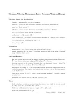
Transcription of Guidelines for Using the Pressure Systems Worksheet
1 Introduction to Conservation Engineering Course Spring 2008 Page 1 of 4 Guidelines for Using the NRCS Pressure Systems Calculation Worksheet 1. Determine the number of animals Using the system : Given choices are: Beef cattle 15 gal/day Beef calves 5 gal/day Milking cows 30 gal/day Dry cows 20 gal/day Sheep 3 gal/day Swine 4 gal/day Horses 12 gal/day Other possible livestock: Llamas 4 gal/day Goats 3 gal/day These amounts may vary depending on how hot or cold the weather is, on how lush the foliage is, and also depending on the weight of the animal.
2 Use your best judgment for your particular situation. The Animal Type box is protected so you cannot manually enter a different animal type than the ones offered. If you prefer, leave it blank, document the correct rate in the Consumption box, and then handwrite the animal type when you have printed your Worksheet . There are only 2 rows to enter animal types. If you have more, you will need to average or pro-rate the consumption amounts together and combine two or more animal types on one row. Clearly document your calculation process by hand on the printout. 2. Determine the water demand the animals will have per typical day: These amounts are generated automatically from the information entered above. The cells are protected and cannot be changed. 3. Determine the Target Supply Rate (TSR): Please note: The program assumes each drinking event is 2 hours (120 minutes) in duration.
3 This is a set time and cannot be changed by the user. The only entry option is the number of drinking events per day. If you prefer that the herd be capable of being watered within a 1 hour time frame, you must enter half of the expected waterings, this will force the program to meet your peak demand flow rate. Introduction to Conservation Engineering Course Spring 2008 Page 2 of 4 Ask the landowner how many times per day the animals go to water. Try to be as accurate as possible. This figure will also vary from season to season. Select the least number of drinking events in order to generate the highest gallons per minute requirement. This information is beneficial as a general guideline for the landowner and well driller to determine if the well output is acceptable. (If the well absolutely cannot provide adequate output, there are other ways to compensate such as increased storage within a holding tank.)
4 Other things to consider are the amount of storage provided for within the well itself.) 4. Source flow rate in gallons per minute: What is the existing or planned pump s output capacity? Ask the landowner, ask the pump supplier, get a copy of the printout from an existing pump, etc. If you do not know the planned pump output, use 10 gpm. This is a common flow rate for many standard pumps. Obvious exceptions to this rule would be if the well is shallow (use 5 gpm) or the well pump is industrial size (use > 10 gpm). IMPORTANT: The default for the next box is Target Supply Rate . Click on the pull-down menu and change this to Rate from Source . The highest friction losses possible in the system will result from the source (ie: pump) output. This is the worst case scenario that you are designing for with typical Pressure Systems .
5 AGAIN, REMEMBER: Change the second box in #4 to Rate from Source . This is critical to the results of the spreadsheet. 5. Measure distance to farthest watering point: This means the distance from the Pressure tank to the farthest planned watering trough. If this is a new system , assume the tank is in close proximity to the planned well location. If there is a major deviation from that normal setup, contact your Area Engineer for assistance in evaluating the system . 6. Determine the vertical elevation difference from the Pressure tank to the highest watering point: Ground elevation at the Pressure tank to ground elevation at the highest trough is close enough for planning purposes. Use a method of determining this elevation difference (ie surveying, GPS, topo maps) that will get you within 20 feet accuracy.
6 Realistically, both the well and trough locations are likely to be moved before the project is completed. Introduction to Conservation Engineering Course Spring 2008 Page 3 of 4 CONSIDER: When selecting pipe diameter, you need to consider the possibility of future expansion of the trough system . A 1-inch pipe may work fine for the planned system but a line will significantly increase the chances of the existing system being able to handle additional pipelines and troughs with only minor, relatively inexpensive changes. As a starting point, a good general guideline would be to use 1-inch diameter pipe in situations where you are planning less than 500 linear feet of pipeline and are very sure there is no potential for expansion. However, you will still need to continue through the calculations to determine if this size pipe will work or not.
7 7. Friction Loss in the pipeline: Box 7a is automatically entered from data in Box 5 above. You cannot change this value here. Box 7b through 7d Notice that there are only 2 options for special fittings. A realistic situation will have more. The difficulty in planning this portion of the spreadsheet is that it is impossible to know the actual pipeline segment lengths (ex: 20 ft. PVC, 100 ft. roll of PE, etc.) unless the landowner has already purchased it. Remember, the goal with this section is to account for friction losses in the pipeline and determine the equivalent length that elbows, tees, couplings, etc. are adding to the planned pipeline. In large enough quantities, friction losses can easily prevent water from reaching and/or filling a trough. Again, design for the worst case scenario. One option to simplify your time in this section is to simply add 50 ft of length to the pipeline for every 1000 ft of total length.
8 For example, if the total system has 2000 feet of pipeline, go back to Box 5 and add 100 feet (2x50) of length to your original total making a new final total of 2100 ft. This will more than compensate for the fittings but not so much that the design will not still be reasonable. Possible WARNING STATEMENTs shown on the spreadsheet here: After you complete section 7, a statement will usually pop up on the screen to comment on your progress. One possible warning statement says that the Friction loss is greater than 10 psi. Confirm that you want to continue? If you do not, you may go back and change the pipe size. The choice is yours in this situation. The program will allow you to continue with the selected pipe diameter. You should keep the warning in mind though, the results on page 2 of the spreadsheet may also indicate that you need to go back and increase the pipe diameter.
9 Introduction to Conservation Engineering Course Spring 2008 Page 4 of 4 8. Expected or needed Pressure at most remote watering point: Watering troughs have minimum operating Pressure requirements. Ask the landowner which company s trough they intend to use. If they do not know, use 10 psi as instructed. Rounding up a bit is a good idea at this point to make extra sure you are getting a good refill rate at the farthest trough. 9. Operating Pressure at the Pressure tank: The numbers in this section are calculated automatically for you but this is still the section where you really need to think about the results. If the operating Pressure is greater than 70 psi, you must redesign the system (as stated in the warning). Standard Pressure tanks will rupture at pressures greater than 70-80 psi. If there is no way to redesign the system , the landowner would need to purchase a more expensive, industrial strength Pressure tank.
10 Standard Pressure switches are 20/40 and 30/50. These are the most cost efficient options. If you get a different size, such as 40/60, consider resizing the pipe diameter. 10. Convert needed data to dynamic head added to the pump by livestock watering system . and 11. Compile the system requirements into a list that the pump supplier can use to size the pump. These two sections are calculated for you and are very important to the well driller or whoever is actually installing the pump in the well. They will use the depth of the actual well and the additional dynamic head to determine the operating requirements for the pump. You do not need to size the pump just make sure they are provided this information!