Transcription of Gusset Plate Stability Using Variable Stress …
1 Gusset Plate Stability Using Variable Stress trajectories Bo Dowswell, , ARC International, 300 Cahaba Park Circle, Suite 116, Birmingham, AL 35242, USA AbstractGusset plates are used in steel buildings and bridges to connect diagonal members to other members in the structural system. In design, Gusset plates are currently modeled as rectangular columns with an effective cross section defined by a 30 Stress trajectory. The buckling strength is calculated Using a standard column curve with empirical effective length factors.
2 Previous tests showed that local yielding allowed the stresses to redistribute and create a wider Stress trajectory. Because slender Gusset plates cannot redistribute stresses without buckling, a Variable Stress trajectory has been established, which is dependent on the lateral buckling slenderness parameter. This paper describes an improved method to calculate the buckling strength of Gusset plates Using Variable Stress trajectory angles. The effective length factors used in design were also analysed, and a Variable effective length factor was proposed.
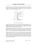
3 The design model is valid for single- and double-plane corner Gusset plates in steel buildings and bridges, including extended corner Gusset plates commonly used for seismic design. Compared to the results of 91 specimens from 12 previously-published research projects, the design model is reasonably accurate. 1. Introduction Figure 1 shows a typical vertical brace connection at a beam-to-column intersection. The Gusset Plate transfers the axial load from the brace to the beam and column.
4 Gusset plates are fabricated in many different configurations; however, only two configurations are addressed in this paper: corner Gusset plates and extended corner Gusset plates. Figure 1: Vertical Brace Connection The corner and extended corner configurations have a single brace framing to the Gusset Plate at the intersection of two other structural members. The Gusset Plate is connected to both Proceedings of the 10thPacific Structural Steel Conference (PSSC 2013)Editors:Richard J.
5 Y. Liew and Siew Chin LeeCopyright 2013 Research Publishing Services. All rights : 978-981-07-7137-9 :: of the 10thPacific Structural Steel Conference (PSSC 2013)members. For corner gussets, the free edges of the Plate are parallel to the connected edges as shown in Figure 2a. For the extended corner configuration, the Gusset Plate is shaped so the free edges are cut at an angle to the connected edges as shown in Figure 2b. a. corner Gusset Plate b. extended corner Gusset Plate Figure 2: Corner and extended corner Gusset Plate configurations 2.
6 Existing Research The existing research on Gusset Stability was reviewed by Dowswell (2006). The research projects included single- and double-plane truss connections typical of bridge construction, as well as corner- and extended-corner Gusset plates commonly used on buildings. Data on corner Gusset plates from Chakrabarti (1987), Brown (1988), Gross and Cheok (1988), Yam and Cheng (1993), Rabinovitch and Cheng (1993), Walbridge et al. (1998), Nast et al.
7 (1999), Sheng et al. (2002) and Hafner (2012) were included in the analysis for this paper. 3. Variable Stress trajectories Using fracture mechanics, Dowswell (2013) showed that the dispersion angle is dependent on geometry, constraint, and inelastic deformation capacity as shown in Figure 3. An analytical model was derived that accounts for all variables affecting the dispersion angle, and the model was shown to properly predict the experimental trends. For Gusset plates, the Stress dispersion angle, , is calculated with Equation 1.
8 2ta6050n 181 . + = (1) where = for Gusset plates with no inelastic capacity = for Gusset plates with inelastic potential Equation 1 predicts a dispersion angle of for plates with no inelastic capacity and for plates with inelastic potential. The effective width, shown in Figure 4a, is calculated with Equation 2. However, in some cases, the calculated effective width can extend beyond the boundaries of the Plate as shown in Figure 4b, causing a smaller effective width than the calculated value.
9 Be = 2ltan (2) where l = length, parallel to the load, of the connection between outermost fasteners 8 Proceedings of the 10thPacific Structural Steel Conference (PSSC 2013) a. Stress free zone ahead of a crack b. dispersion angle vs. normalized strain Figure 3: Stress trajectories a. calculated effective width b. maximum effective width Figure 4: Effective width To determine , the level of inelastic potential, , must be estimated based on the slenderness of the Plate . Because the lateral buckling strength of the equivalent column is based on the AISC column curve, can be calculated Using AISC Specification (AISC, 2010) Section E3.
10 The column curve is in the inelastic range when r, where r = and is calculated with Equation 3. yFKLrE = (3) where E = modulus of elasticity Fy = specified minimum yield strength K = effective length factor L = column length r = radius of gyration = slenderness parameter r = limiting slenderness parameter between elastic and inelastic behavior 9 Proceedings of the 10thPacific Structural Steel Conference (PSSC 2013)Combining Equations 1 and 3, a simple estimate of the dispersion angle is ymFKLtE= (4)