Transcription of GV60 Remote Electronic Ignition and Control System
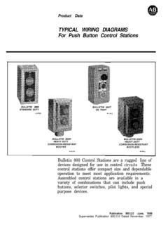
1 GV60 Remote Electronic Ignition and Control System INSTALLER TROUBLESHOOTING GUIDE. If the information in this manual is not followed exactly, a fire or explosion may result causing property damage, personal injury or loss of life. WARNING TO THE APPLIANCE OWNER. For your safety, read the user instructions before attempting to light the appliance. BEFORE OPERATING smell all around the appliance area for gas. Be sure to smell next to the floor because some gas is heavier than air and will settle on the floor. WHAT TO DO IF YOU SMELL GAS. Do not try to light any appliance. Do not touch any electrical switch; do not use any phone in your building. Immediately call your gas supplier from a neighbor's phone.
2 Follow the gas supplier's instructions. If you cannot reach your gas supplier, call the fire department. Do not store or use gasoline of other flammable vapors and liquids in the vicinity of this Control or other appliances. GENERAL NOTES: Wiring of valve and receiver must be completed before starting Ignition . Installation and service must be performed by a qualified installer, service agency or the gas supplier. The installation must conform with local codes or in the absence of local codes, with the National Fuel Gas Code, ANSI 54 or The International Fuel Gas Code or in Canada. All piping must comply with local codes and ordinances. Tubing installation must comply with approved standards and practices.
3 Do not use this Control or any gas appliance if any part has been under water. Immediately call a qualified service technician to inspect the Control and or gas appliance and to replace any part of the Control System and any gas Control which has been under water. 1 of 5. GV60 Remote Electronic Ignition and Control System INSTALLER TROUBLESHOOTING GUIDE. OBSERVED PROBLEM: POSSIBLE CAUSE: REMEDY: A) No Transmission: 1. Receiver must learn new code: 1. Press and hold the receiver's (motor does not turn) reset button until you hear 2. acoustic signals. After the second longer acoustic signal, release the reset button and within the subsequent 20. seconds, press the (down arrow) on the Remote handset until you hear an additional long acoustic signal confirming the new code is set (see figure 1).
4 Creating an electrical short between the batteries/battery box and metal parts of the appliance may render the receiver inoperable (see figure 2). Reset Figure 1: Receiver with Reset button 2. Dead batteries. 2. Replace the batteries. 3. The receiver is surrounded by 3. Change the position of the metal, reducing the antenna. transmission range. 4. Receiver 4. Replace receiver and reprogram code (remedy 1). 5. Transmitter 5. Replace the transmitter and reprogram code (remedy 1). Figure 2. 6. Wiring at valve damaged. 6. Replace valve. 7. Bent pins on 8 wire connector. 7. Straighten pins on 8 wire connector. 2 of 5. GV60 Remote Electronic Ignition and Control System INSTALLER TROUBLESHOOTING GUIDE.
5 OBSERVED PROBLEM: POSSIBLE CAUSE: REMEDY: Make sure that the antenna is not too close to the electrode cable and Ignition coil (beneath the cover). It will damage the receiver (see figure 3). correct position of antenna electrode cable antenna Figure 3 Figure 4. B) No Ignition ; No Tone: 1. Receiver 1. Replace receiver and reprogram code ( remedy 1). C) No Ignition ; One 5 second 1. ON/OFF switch is in OFF 1. Push switch to ON position. continuous tone (7 short beeps position. might be heard prior to the 5. second tone): 2. Loose wire. 2. Secure wire. 3. Receiver 3. Replace receiver and reprogram code ( remedy 1). 4. Bent pins on 8 wire 4. Straighten pins on 8 wire connector. connector.
6 5. Valve 5. Replace valve. 3 of 5. GV60 Remote Electronic Ignition and Control System INSTALLER TROUBLESHOOTING GUIDE. OBSERVED PROBLEM: POSSIBLE CAUSE: REMEDY: D) No Pilot Flame and Control 1. Air in the pilot supply line. 1. Purge the line or start Ignition continues to spark: several times. 2. No spark at pilot burner. 2. Check spark gap; check wiring connection. Check for spark in location along cable. 3. Valve 3. Replace valve. Do not over tighten the thermocuple interrupter. 4. Over tightened 4. Replace valve and thermocouple interrupter. thermocouple interrupter. 5. Receiver 5. Replace receiver and reprogram code (remedy 1). E) Pilot is lit and Control continues to 1. Receiver 1.
7 Replace receiver and spark. Valve shuts off after reprogram code (remedy 1). seconds. Valve operates manually. F) Pilot is lit and sparking stops. 1. Not enough voltage generated 1. Use a digital multimeter set in Valve shuts off after from the thermocouple or too the mV range and measure seconds. Valve does not operate much resistance in the the voltage by connecting the manually. circuit. test leads to the spade connector. Spade connector is Note: For manual operation turn the Note: To find which part of the located on the outer surface, valve knob to the manual position circuit is causing the problem, a directly beside the magnet and hold the safety magnet open checklist for each application can nut.
8 (see figure 6). The with a pen for approximately 60 be prepared using an Excel available voltage must be at seconds (see figure 5). calculaton available from Mertik least 5mV. The manufacturer Maxitrol. must specify the drop time for the application. The drop time Possible parts are: can be measured after the ON-OFF switch, Temperature thermocouple is heated. switches, Thermo current connections, Receiver. Figure 5 Figure 6. 4 of 5. GV60 Remote Electronic Ignition and Control System INSTALLER TROUBLESHOOTING GUIDE. OBSERVED PROBLEM: POSSIBLE CAUSE: REMEDY: F) Pilot is lit and sparking stops. 2. Thermocouple 2. Replace thermocouple. Valve shuts off after seconds. Valve does not operate 3.
9 Low inlet pressure. 3. Confirm regulator pressure manually. and sizing. Replace if necessary. 4. Valve 4. Replace valve. Do not over tighten the thermocouple interrupter. G) 3 short beeps while the motor 1. Batteries are low. 1. Replace batteries. turns: Creating an electrical short between the batteries/battery box and metal parts of the appliance may render the receiver inoperable (see figure 2). H) Pilot flame lights but there is no 1. Manual override knob 1. Turn Manual override knob to main gas flow. (if equipped) is in MAN postion. ON position (see figure 4). 2. Valve turned down to pilot flow. 2. Turn flame to high fire by pressing up button on Remote handset. 3. Low inlet pressure.
10 3. Confirm regulator pressure, and sizing. Replace valve if necesary. 4. Valve. 4. Replace valve. Maxitrol Company 23555 Telegraph Rd., Southfield, MI 48037 Copyright 2005 Maxitrol 5 of 5 Company All Rights Reserv