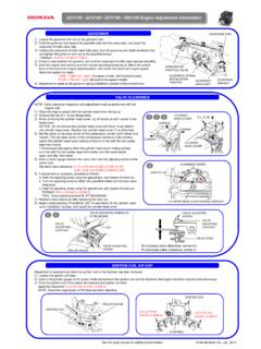
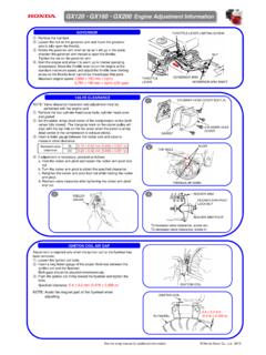
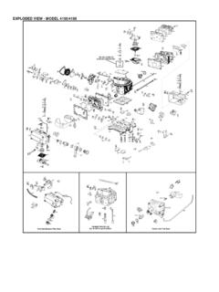
Transcription of GX120 GX160 GX200 Engine Assembly Information
1 VALVE LIFTERPUNCH MARKSCAMSHAFTEXHAUST VALVEINTAKE VALVEVALVE GUIDE (2)VALVE SPRING (2)VALVE SPRING RETAINERVALVE ROTATOR (Exhaust valve only)NOTICE:If the valve rotator is not installed, theexhaust valve may drop into the cylinderwhen starting the HEADROCKER ARMPIVOT LOCK NUT (2)10 N m ( kgf m, 7 lbf ft)ROCKER ARM PIVOT (2)PUSH ROD (2)REASSEMBLY:Check both ends for wear,and check the rod sure the rod ends arefirmly seated in the ARM (2)REASSEMBLY:Before installing, check for wear on the surfaces which contactthe pivot bolt, the push rod, and the rocker arm ARM PIVOT BOLT (2) 24 N m ( kgf m, 17 lbf ft)VALVE STEM SEAL (Intake valve only)INTAKE VALVEREASSEMBLY: Do not interchange with the exhaust valve.
2 Valve head diameter: Intake: 25 mm ( in) Exhaust: 24 mm ( in) Be careful not to damage the valve stem seal when PINS8 x 55 (4) ( GX120 ), 8 x 60 (4) ( GX160 / GX200 )24 N m ( kgf m, 17 lbf ft)REMOVAL/INSTALLATION:Loosen and tighten thebolts in a crisscross patternin 2-3 RING (CHROME FACED)PISTONPISTON PINPISTON PIN CLIPREASSEMBLY:Install by setting one end of the clip inthe piston groove, holding the otherend with long-nosed pliers, androtating the clip not align the end gap of the clipwith the cutout in the piston pin : Install theconnecting rod with thelong end toward thetriangle-marked side ofthe : Install all rings with the markings facing upward. Be sure that the top and second rings are not interchanged.
3 Check that the rings rotate smoothly after installation. Space the piston ring end gaps 120 degrees apart, and do not align the gaps with the piston pin bore. Space the oil ring side rail end gaps at least 10 mm ( in) apart. Coat the oil ring with oil after RING (BLACK FACED)OIL RING (COMBINATION RINGS)PISTON RINGPISTONPISTONCRANKCASE COVER/CRANKSHAFT/PISTON CYLINDER HEAD/VALVESGX120 GX160 GX200 Engine Assembly InformationREASSEMBLY:Install with thetriangle marktoward thepushrod :Push in until the bearing touchesthe crankcase. Be careful not todamage the oil ROD BOLT12 N m ( kgf m, 9 lbf ft)6 x 28 ( GX120 )12 N m ( kgf m, 9 lbf ft)8 x 32 ( GX160 / GX200 )24 N m ( kgf m, 17 lbf ft)CRANKCASE COVERCRANKCASECRANKSHAFTCONNECTING ROD CAPREASSEMBLY: With the crankshaft in place, align the timing punch mark on the cam gear with the punch mark on the crankshaft gear.
4 Before installing, inspect for worn and weakened springs and check that the decompressor weight moves GEARREASSEMBLY:Install the liftersimmediately beforeinstalling the MARKPUSH ROD HOLEPUNCH MARKSCUT-OUTOIL SEAL 22 x 35 x 6 mm ( GX120 )25 x 41 x 6 mm( GX160 / GX200 )GREASOIL SEAL22 x 41 x 6 mm ( GX120 )25 x 41 x 6 mm ( GX160 / GX200 )GREASBALLBEARINGREASSEMBLY: Install with the oil dipper toward the camshaft and theribs on the cap and connecting rod are aligned. Honda Motor Co., Ltd. 2009 SECOND RING(BLACK FACED)OIL RING(COMBINATION RINGS)TOP RING(CHROME FACED)GOVERNOR DRIVEGEARCRANKCASECOVERGASKETDo not :Push down and slide the retainer to the side, so the valvestem slips through the hole at the side of the :The exhaust valve retainer has a larger center recess thanthe intake valve retainer so it can accept the valve :Do not remove the valve spring retainers while the cylinderhead is installed, or the valves will drop into the : Before installation, remove carbon deposits and inspect the valve.
5 Do not interchange with the intake HEAD DIAMETERGX120: IN: 22 mm ( in) EX: 19 mm ( in) GX160 : IN: 25 mm ( in) EX: 24 mm ( in) CYLINDER HEADCYLINDER BARRELDo not DRAINBOLT18 N m( kgf m,13 lbf ft)DRAIN BOLT : GX200 :Refer to the above for Information not shown with a new onewhen : Before installation, remove any carbon deposits from the combustion chamber and inspect the valve seats. Measure the cylinder compression after HEADO-RINGOIL LEVEL SWITCH6 x 12 (2)REASSEMBLY:The lock pin must beinstalled with thestraight side of the pinagainst the groove inthe PINGOVERNORARM SHAFT10 mm NUTWASHER (2)REASSEMBLY: Be sureto install the governorweight before installingthe :Install insidethe WEIGHTCLIPGOVERNOR SLIDERREASSEMBLY:Insert firmlyinto the : Install firmly in the ( To Engine switch)Green ( To side plate)See the shop manual for additional Information .