Transcription of Handler 120 / 150 And Piecemaker 14A Gun
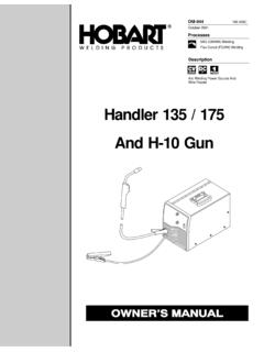
1 ProcessesOM-210 088 DNovember 1999 Handler 120 / 150 AndPiecemaker 14A GunArc Welding Power Source And WireFeederDescriptionMIG (GMAW) WeldingFlux Cored (FCAW) WeldingHobart Welders manufactures a full lineof welders and welding related information on other quality Hobartproducts, contact your local Hobart distributorto receive the latest full line catalog orindividual catalog sheets. To locate your nearestdistributor or service agency call you and congratulations on choosing you can get the job done and get it done know you don t have time to do it any other Owner s Manual is designed to help you get themost out of your Hobart products. Please take timeto read the Safety precautions. They will help youprotect yourself againstpotential hazards on theworksite. We ve madeinstallation and operationquick and easy. With Hobart you can count onyears of reliable service with propermaintenance.
2 And if for some reason the unitneeds repair, there s a Troubleshooting sectionthat will help you figure out what the problemis. The parts list will then help you to decidewhich exact part you may need to fix theproblem. Warranty and service information foryour particular model are also is registered to theISO 9001 Quality Hobart to YouHobart offers a TechnicalManual which providesmore detailed service andparts information for yourunit. To obtain a TechnicalManual, contact your localdistributor. Your distributorcan also supply you withWelding Process Manualssuch as SMAW, GTAW,GMAW, and following terms areused interchangeablythroughout this manual:MIG=GMAWTABLE OF CONTENTSSECTION 1 SAFETY PRECAUTIONS - READ BEFORE USING1.. 1-1. Symbol Usage1.. 1-2. Arc Welding Hazards1.. Symbols for Installation, Operation, and Maintenance3.. 1-4. Principal Safety Standards3.
3 Information4.. SECTION 1. CONSIGNES DE SECURITE LIRE AVANT UTILISATION5.. des symboles5.. relatifs au soudage l arc5.. suppl mentaires en relation avec l installation, le fonctionnementet la maintenance7.. normes de s curit 8.. sur les champs lectromagn tiques8.. SECTION 2 SPECIFICATIONS9.. 2-1. Specifications9.. 2-2. Duty Cycle And Overheating10.. 2-3. Volt-Ampere Curves11.. SECTION 3 INSTALLATION12.. Welding Gun12.. Polarity12.. 3-3. Process/Polarity Table12.. 3-4. Installing Gas Supply13.. A Location And Connecting Input Power For 120 VAC Model14.. A Location And Connecting Input Power For 230 VAC Model15.. 3-7. Electrical Service Guide For 230 VAC Model16.. Wire Spool And Adjusting Hub Tension16.. Welding Wire17.. SECTION 4 OPERATION18.. 4-1. Controls18.. 4-2. Weld Parameters For 120 VAC Model19.. 4-3. Weld Parameters For 230 VAC Model20.
4 SECTION 5 MAINTENANCE &TROUBLESHOOTING21.. Maintenance21.. 5-2. Overload Protection21.. 5-3. Changing Drive Roll Or Wire Inlet Guide22.. 5-4. Replacing Gun Contact Tip22.. Or Replacing Piecemaker 14-A Gun Liner23.. 5-6. Troubleshooting Table24.. SECTION 6 ELECTRICAL DIAGRAM26.. SECTION 7 MIG WELDING (GMAW) GUIDELINES29.. 7-1. Typical MIG Process Connections29.. 7-2. Typical MIG Process Control Settings30.. And Positioning Welding Gun31.. That Affect Weld Bead Shape32.. Movement During Welding33.. Weld Bead Characteristics33.. Weld Bead Characteristics33.. 7-8. Troubleshooting Excessive Spatter34.. 7-9. Troubleshooting Porosity34.. 7-10. Troubleshooting Excessive Penetration35.. 7-11. Troubleshooting Lack Of Penetration35.. 7-12. Troubleshooting Incomplete Fusion35.. 7-13. Troubleshooting Burn-Through36.. 7-14. Troubleshooting Waviness Of Bead36.
5 7-15. Troubleshooting Distortion36.. MIG Shielding Gases37.. SECTION 8 PARTS LIST38.. WARRANTYOM-210088 DOM-210 088 Page 1 SECTION 1 SAFETY PRECAUTIONS - READ BEFORE USINGsom _nd_4/981-1. Symbol UsageMeans Warning! Watch Out! There are possible hazardswith this procedure! The possible hazards are shown inthe adjoining a special safety Note ; not safety group of symbols means Warning! Watch Out! possibleELECTRIC SHOCK, MOVING PARTS, and HOT PARTS symbols and related instructions below for necessary actionsto avoid the Arc Welding HazardsYThe symbols shown below are used throughout this manual tocall attention to and identify possible hazards. When you seethe symbol, watch out, and follow the related instructions toavoid the hazard. The safety information given below is onlya summary of the more complete safety information found inthe Safety Standards listed in Section 1-4.
6 Read and follow allSafety qualified persons should install, operate, maintain, andrepair this operation, keep everybody, especially children, SHOCK can live electrical parts can cause fatal shocksor severe burns. The electrode and work circuit iselectrically live whenever the output is on. The inputpower circuit and machine internal circuits are alsolive when power is on. In semiautomatic or automatic wire welding, thewire, wire reel, drive roll housing, and all metal parts touching thewelding wire are electrically live. Incorrectly installed or improperlygrounded equipment is a not touch live electrical dry, hole-free insulating gloves and body yourself from work and ground using dry insulating matsor covers big enough to prevent any physical contact with the workor not use AC output in damp areas, if movement is confined, or ifthere is a danger of AC output ONLY if required for the welding AC output is required, use remote output control if present input power or stop engine before installing orservicing this equipment.
7 Lockout/tagout input power according toOSHA 29 CFR (see Safety Standards).DProperly install and ground this equipment according to itsOwner s Manual and national, state, and local verify the supply ground check and be sure that inputpower cord ground wire is properly connected to ground terminal indisconnect box or that cord plug is connected to a properlygrounded receptacle making input connections, attach proper grounding conduc-tor first double-check inspect input power cord for damage or bare wiring replace cord immediately if damaged bare wiring can off all equipment when not in not use worn, damaged, undersized, or poorly spliced not drape cables over your earth grounding of the workpiece is required, ground it directlywith a separate not touch electrode if you are in contact with the work, ground,or another electrode from a different only well-maintained equipment.
8 Repair or replace damagedparts at once. Maintain unit according to a safety harness if working above floor all panels and covers securely in work cable with good metal-to-metal contact to workpieceor worktable as near the weld as work clamp when not connected to workpiece to preventcontact with any metal not connect more than one electrode or work cable to anysingle weld output DC VOLTAGE exists after removal ofinput power on Off inverter, disconnect input power, and discharge inputcapacitors according to instructions in Maintenance Sectionbefore touching any produces fumes and gases. Breathingthese fumes and gases can be hazardous to AND GASES can be your head out of the fumes. Do not breathe the inside, ventilate the area and/or use exhaust at the arc to removewelding fumes and ventilation is poor, use an approved air-supplied the Material Safety Data Sheets (MSDSs) and themanufacturer s instructions for metals, consumables, coatings,cleaners, and in a confined space only if it is well ventilated, or whilewearing an air-supplied respirator.
9 Always have a trained watch-person nearby. Welding fumes and gases can displace air andlower the oxygen level causing injury or death. Be sure the breath-ing air is not weld in locations near degreasing, cleaning, or spraying op-erations. The heat and rays of the arc can react with vapors to formhighly toxic and irritating not weld on coated metals, such as galvanized, lead, orcadmium plated steel, unless the coating is removed from the weldarea, the area is well ventilated, and if necessary, while wearing anair-supplied respirator. The coatings and any metals containingthese elements can give off toxic fumes if 088 Page 2 Arc rays from the welding process produce intensevisible and invisible (ultraviolet and infrared) raysthat can burn eyes and skin. Sparks fly off from RAYS can burn eyes and a welding helmet fitted with a proper shade of filter to protectyour face and eyes when welding or watching (see ANSI listed in Safety Standards).
10 DWear approved safety glasses with side shields under protective screens or barriers to protect others from flash andglare; warn others not to watch the protective clothing made from durable, flame-resistant mate-rial (leather and wool) and foot on closed containers, such as tanks,drums, or pipes, can cause them to blow up. Sparkscan fly off from the welding arc. The flying sparks, hotworkpiece, and hot equipment can cause fires andburns. Accidental contact of electrode to metal objects can causesparks, explosion, overheating, or fire. Check and be sure the area issafe before doing any can cause fire or yourself and others from flying sparks and hot not weld where flying sparks can strike flammable all flammables within 35 ft ( m) of the welding arc. Ifthis is not possible, tightly cover them with approved alert that welding sparks and hot materials from welding caneasily go through small cracks and openings to adjacent for fire, and keep a fire extinguisher aware that welding on a ceiling, floor, bulkhead, or partition cancause fire on the hidden not weld on closed containers such as tanks, drums, or pipes,unless they are properly prepared according to AWS (seeSafety Standards).