Transcription of HARD TO FILL FUEL TANK - InfinitiG37.com
1 1/8 Classification: Reference: Date: FE08-004a ITB08-041a October 28, 2008 hard TO fill fuel TANK Applied Vehicles has been amended and the Classification was changed to FE. No other content has changed. Please discard all earlier versions. APPLIED VEHICLES: 2003 2006 G35 Sedan (V35) 2007 2008 G35 Sedan (V36) 2003 2007 G35 Coupe (CV35) 2008 G37 Coupe (CV36) 2006 2008 M (Y50) IF YOU CONFIRM The fuel tank is difficult to fill more than , NOTE: Filling nozzle continues to click OFF when the fuel tank is more than full. ACTIONS Install the Cut Bracket (cover) onto the fill Limit Vent Valve (FLVV) inside the fuel tank (see Service Procedure). NOTE: All fuel must be removed from the tank for this procedure.
2 IMPORTANT: The purpose of "ACTIONS" (above) is to give you a quick idea of the work you will be performing. You MUST closely follow the entire Service Procedure as it contains information that is essential to successfully completing this repair. Infiniti Bulletins are intended for use by qualified technicians, not 'do-it-yourselfers'. Qualified technicians are properly trained individuals who have the equipment, tools, safety instruction, and know-how to do a job properly and safely. NOTE: If you believe that a described condition may apply to a particular vehicle, DO NOT assume that it does. See your Infiniti dealer to determine if this applies to your vehicle. PARTS INFORMATION Description PART # Quantity Cut Bracket - (FLV Valve Cover) 17366 EY80A 1 O-ring (for fuel pump opening) 17342 01A00 1 CLAIMS INFORMATION Submit a Primary Part (PP) type line claim using the following claims coding: G35 (V35) Sedan, G35 (CV35) Coupe, G35 (V36) Sedan, G37 (CV36) Coupe.
3 DESCRIPTION PFP OP CODE SYM DIA FRT FLV Valve Cover Install (1) FX32AA ZE 32 hrs (1) Reference the FAST Parts Catalog and use the applicable Tank Assy- fuel P/N as the PFP OR: M35/45 (Y50) with non-power seat DESCRIPTION PFP OP CODE SYM DIA FRT FLV Valve Cover Install (1) FX32AA ZE 32 hrs (1) Reference the FAST Parts Catalog and use the applicable Tank Assy- fuel P/N as the PFP OR: M35/45 (Y50) with power seat DESCRIPTION PFP OP CODE SYM DIA FRT FLV Valve Cover Install (1) FX33AA ZE 32 hrs (1) Reference the FAST Parts Catalog and use the applicable Tank Assy- fuel P/N as the PFP 2/8 ITB08-041a SERVICE PROCEDURE NOTE: The procedure in this bulletin will require placing your entire arm into the fuel tank. The fuel tank must be empty for this procedure.
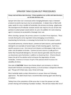
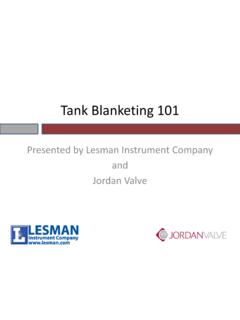
4 1. Remove the fuel pump from the fuel tank. Refer to Section FL in the Service Manual for fuel pump removal information. CAUTION: The fuel tank is required to be less than 7/8 full before removing the fuel pump in order to prevent fuel spillage from the fuel pump opening. 2. Cut / split the side of a piece of rubber tube (vacuum line) and place it on the edge of the fuel pump opening. This will protect your hands and arms from the sharp edge of the fuel tank. Rubber hose Figure 1 Before continuing with this procedure: Make sure the fuel tank is empty . Read through all of the steps and understand the procedure. 3/8 ITB08-041a 3. Hold the Cut Bracket (cover) so the open side of the cover is towards the passenger side of the vehicle. NOTE: There is very little room inside the tank to maneuver the cover.
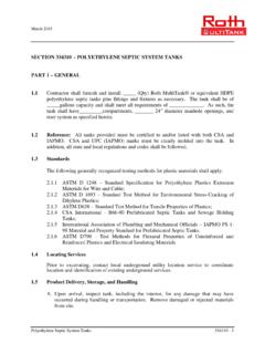
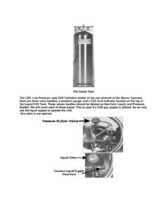
5 You should hold it in the installation direction as you put it into the tank. Figure 2 4. While holding the cover, reach into the tank. Passenger side Cover for FLV valve FLV Valve is in this area. Figure 3 4/8 ITB08-041a 5. Maneuver the cover to the FLV valve and snap the cover onto the valve. The FLV valve is located in the middle upper area of the tank. Refer to Figures 4 through 8. The side of the fuel tank has been cut away to show installation of the cover. fuel pump opening Cover FLV Valve Figure 4 See Photos on the next two pages (Figures 5 8). 5/8 ITB08-041a Snap cover into place from this side Then turn / twist the cover into position.
6 Figure 5 Cut Bracket (cover) installed on FLV valve. Tabs hold the cover tight on the sides of the FLV valve. Clip at the top of the cover clips onto the port on top of the FLV valve. Open side of cover Figure 6 6/8 ITB08-041a FLV valve without cover Port at top of FLV Valve Figure 7 View from inside the tank with the cover installed on the FLV valve Figure 8 7/8 ITB08-041a 6. Use a mirror to confirm the cover is installed correctly. Figure 9 7. Reinstall all parts removed in reverse order. NOTE: Make sure to use a new O-ring (P/N 17342 01A00) on the fuel pump opening. 8/8 ITB08-041a