Transcription of Hardware Manual CNC760 - Eding CNC
1 Copyright 2018 by Eding CNC Hardware Manual CNC760 Revision 4 22 February, 2018 Released Hardware Manual CNC760 Page | 2 History: Revision overview: Revision Date Author 1 22-5-2017 AB 2 23-6-2017 AB 3 6-12-2017 AB 4 22-2-2018 AB Revision Remarks 1 Initial version. 2 Fixed typo s in AUX-IN overview 3 Correcting pinning HOME connector 4 Correcting ALM+/- on axis outputs. Added clearifications. Hardware Manual CNC760 Page | 3 Table of contents 1 Introduction .. 4 Purpose .. 4 Scope .. 4 2 Board overview .. 5 3 Board jumpers and indicators .. 6 JP9, JP10, JP11 .. 6 LED indications (LED2-LED6) .. 7 4 Connectors .. 9 Power.
2 9 Network .. 10 RS485 .. 11 AUX-OUT .. 12 AUX-IN .. 15 CNC-OUT .. 17 CNC-IN .. 19 MPG .. 23 HOME-IN .. 25 PWM-OUT .. 28 ANALOG-IN .. 30 Extruder E1-E4 .. 31 Axis A1-A6 .. 33 5 Configuring the analogue outputs .. 39 6 Getting started .. 40 Hardware Manual CNC760 Page | 4 1 Introduction Purpose This Manual desribebdes the Hardware of the CNC760 . The CNC760 is a 6-asix CNC controller with addional 4 extruder controllers. The basic specification is: Scope This document describes the Hardware of the CNC760 . 6x axis controller interface Puls/Direction 5V (max. 400 Khz) Enable 5V or open-collector (max. 24V) Alarm 4x extruder interface Enable/Direction/Step 5V 6x digital HOME inputs 24V 10x digital outputs Open collector (max.)
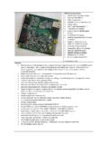
3 24V) 10x digital inputs 24V 8x analog inputs (12 bits) 2x analog outputs 0-10V 2x cooling outputs Open collector (max. 24V) 8x PWM outputs Open collector (max. 24V) Safety relay I/O Output System Ready Output for safety relay (Watchdog) Open Collector Input External Error 24V Input E-Stop 24V 1x Length detection input (Probe) 24V 1x Spindle encoder input 5V input 1x RS485 interface RS485, MODBUS compatible (for connecting extra I/O or functionality, cable length up to 20m) Handwheel interface (Pendant) 2x digital input 5V 2x MPG input 5V 2x dedicated analog input Interface 100 Mbit Ethernet Power Supply 24 VDC Dimension 230x107mm (suitable for DIN rail mounting) Others Firmware upgradable through network connection Hardware Manual CNC760 Page | 5 2 Board overview The image below shows an overview of the CNC760 .
4 Hardware Manual CNC760 Page | 6 3 Board jumpers and indicators JP9, JP10, JP11 With these jumpers, several settings can be forced: JP9 Reserved JP10 Startup with default IP address JP11 Skip bootloader JP11 JP9 JP10 Hardware Manual CNC760 Page | 7 LED indications (LED2-LED6) The board uses several LEDs indicating activity. Power LEDs: LED1: indicates that the external power is connected, this means that 24V and 5V are available. PWR: this LED indicates that the power for the processor is available ( ). Power Network Status Hardware Manual CNC760 Page | 8 Network LEDs: Yellow = Network activity Green = Network connection Status LEDS: LED6 RED SYSREADY, indicates when CNC system is ready for operation.
5 Can be used in cooperation with safety relay. LED5 RED WATCHDOG charge pump, indicates operation of the watchdog circuitry LED4 GREEN Controller heartbeat indicating the board is active LED3 GREEN Indicates Machine On LED2 GREEN Flashing when application is starting up. After startup, will be switch ON if E-STOP occurred. Please note, when in bootloader mode LED2 and LED3 will toggle to indicate this. LED2 LED6 Hardware Manual CNC760 Page | 9 4 Connectors Power The voltage of the supplied power is 24V DC. Warning: Due to a protection diode at the input the 24V that is available on a number of connectors will be a bit lower, please check when connecting 24V devices to that connector if they will operate correctly.
6 Warning: Although the 24V is also available on numerous connectors, it is advisable to use separate wiring for powering 24V devices if much current is needed. The image below shows the power connector. Warning: Check the polarity of the power, damage to the board may occur if the polarity is reversed. Hardware Manual CNC760 Page | 10 Network The board needs to be connected via cross cable of type CAT5 or CAT5E. We advise to use properly shielded network cables type SF/UTP. The default IP address is Note: Make sure that the PC that the board is connected to is correctly setup and has the correct IP address, make sure there is no IP address conflict. Hardware Manual CNC760 Page | 11 RS485 Via the RS485 connector external Hardware can be connected.
7 RS485 is a balanced signal, this decreases susceptibility to interference. The protocolled that is used is MODBUS. The image below shows a close up of the connector. The connector consists out of 4 signals: COM Common B Balanced signal A IRQ IRQ Input for external interrupt COM B A IRQ Hardware Manual CNC760 Page | 12 AUX-OUT The auxiliary outputs can be used for switching external devices. Pin #1 Pin #2 Hardware Manual CNC760 Page | 13 Below an overview of all connections of this connector: Warning: The total combined current of the 24V outputs should not exceed 1A The auxiliary outputs are open-collector outputs. An open-collector output means it switches the connected wire to GND.
8 This enables the user to switch devices that do not need the same voltage rating as the controller has. In the image below such an output is shown. Figure 1 Open collector output. This output can directly be used, for example, to switch a relay. If a logic signal is needed a pull-up resistor is required. Pin # Name Direction Type Function Electrical Spec. Remarks 1 GND GROUND 2 GND GROUND 3 AUX OUT1 OUTPUT Open Collector Aux Output 1 Max. rating 50V/500mA Optional used for controlling 0-10V output1 4 SYSRDY OUTPUT Open Collector System Ready Max. rating 50V/500mA System Ready, indicates that system is ready for operation. 5 AUX OUT2 OUTPUT Open Collector Aux Output 2 Max.
9 Rating 50V/500mA Optional used for controlling 0-10V output2 6 AUX OUT9 OUTPUT Open Collector Aux Output 9 Max. rating 50V/500mA Shared with AEE3 7 AUX OUT3 OUTPUT Open Collector Aux Output 3 Max. rating 50V/500mA 8 AUX OUT10 OUTPUT Open Collector Aux Output 10 Max. rating 50V/500mA Shared with AEE4 9 AUX OUT4 OUTPUT Open Collector Aux Output 4 Max. rating 50V/500mA 10 GND GROUND 11 AUX OUT5 OUTPUT Open Collector Aux Output 5 Max. rating 50V/500mA 12 GND GROUND 13 AUX OUT6 OUTPUT Open Collector Aux Output 6 Max. rating 50V/500mA 14 GND GROUND 15 AUX OUT7 OUTPUT Open Collector Aux Output 7 Max. rating 50V/500mA Shared with AEE1 16 PWM-VOLT2 OUTPUT PWM or 0-10V, see also Configuring the analogue outputs 17 AUX OUT8 OUTPUT Open Collector Aux Output 8 Max.
10 Rating 50V/500mA Shared with AEE2 18 GND GROUND 19 +24V POWER +24V/1A 20 +24V POWER +24V/1A Please note, an open-collector output can not be measured with eg. a multimeter, to test an output connected a 10k resistor between output and +5V or 24V, now you should be able to measure this output switching. Hardware Manual CNC760 Page | 14 Warning: Connecting an open-collector output directly to a positive voltage eg. 24V will cause a short-circuit damaging the board. The drawing below shows how an open-collector output connector can be used to create different output signal levels by using a pull-up resistor. The value of this resistor can vary depending on the load of the output.