Transcription of HART Field Device Specification Fisher FIELDVUE …
1 Field Device SpecificationFisherr FIELDVUE DVC6200 Digital ValveControllerHART RevisionDevice TypeDevice RevisionFirmware RevisionHART 50913, 4, 5, 6 hart of this and Valve Jumpers and Practice Device A Compatibility B DVC6200 Parameters as part of a Rosemountr 1410/1420 WirelessHARTr Manual SupplementD103639X012 DVC6200 Digital Valve ControllerAugust 2014W9713 Instruction Manual SupplementD103639X012 DVC6200 Digital Valve ControllerAugust 20142 IntroductionProduct OverviewThe FIELDVUE DVC6200 digital valve controller is designed to control the pneumatic actuator of a process controlvalve.
2 It receives a current signal from a host and uses instrument air supply to create a metered pressure output signalto the pneumatic actuator. Movement of the actuator as it positions the process control valve is measured by theDVC6200 travel sensor as its primary feedback. The name plate is located on the bottom side of the DVC6200 mastermodule assembly and indicates the model name, individual product serial number, and any applicable third of this documentThis Specification is designed to be a technical reference for hart capable host application developers, systemintegrators and knowledgeable end-users.
3 It also provides functional specifications ( , commands, enumerationsand performance requirements) used during Field Device development, maintenance and testing. This documentassumes the reader is familiar with hart Protocol requirements and terminology. Additional product information isavailable in DVC6200 product literature, available from Emerson Process and definitionsARAlert RecordConfigurationVariablesVariables which represent nonvolatile values of manufacturing initialized data oruser specified configuration information. These variables cannot be enumerated viaCommand 54 and as such stand on their own with no associated units or range VariableMeasured variables that are exposed to hart and can be enumerated using Command there are variables whose ID is in the range of 0 to 13 and are associated with unitscodes, status, and range pre-defined set of values or Variable, a physical input to the Variable a logical point inside the Device , hard mapped to a given MV as the sourceof NV term that applies to diagnostic data packets.
4 It is defined as a collection of periodicallysampled variables captured at a single instant in time. It does not include the Monitor PORT A output pressure which increases with increasing drive PORT B output pressure which decreases with increasing drive Stroke Test, a limited form of ramped valve 8 bit unsigned 16 bit unsigned to the IEEE 754 floating point ASCIIA special form of characters defined by hart in which 6 bit ASCII characters are packed intobyte SpanFormatA proprietary 16 bit integer format for numerical values used by some of this Device s DeviceSpecific Manual SupplementD103639X012 DVC6200 Digital Valve ControllerAugust 20143 Reference DocumentationHART Smart Communications Protocol Specification Revision.
5 A group of documents specifying the HARTC ommunication Protocol, physical layers, and Data Link Layers as defined by the hart Communications :DVC6200 Fisher FIELDVUE DVC6200 Digital Valve Controller (D103415X012) Fisher FIELDVUE DVC6200 Series Digital Valve Controllers Quick Start Guide (D103556X012) Fisher FIELDVUE DVC6200 Digital Valve Controller (HW 2) Instruction Manual (D103605X012) Device IdentificationManufacturer NameFisher ControlsModel Name(s)DVC6200 Manufacture ID Code19(13 Hex) Device Type Code09(09 Hex) hart Protocol Revision2 User Selectable hart Revisionbetween hart 5 and hart 7 YesNumber of Device Variables13 Physical Layers SupportedFSKP hysical Device CategoryValve PositionerInstruction Manual SupplementD103639X012 DVC6200 Digital Valve ControllerAugust 20144 Product InterfacesControl Valve InterfaceThe DVC6200 digital valve controller is mechanically attached to the valve s actuator by means of a mounting control valve's position is conveyed to the travel sensor of the DVC6200 digital valve controller by means of thefeedback bracket and
6 Magnet assembly attached to the actuator s VALVECONTROLLERFEEDBACK BRACKETAND MAGNET ASSEMBLYX0381-1 Pneumatic tubing connected to the DVC6200 brings instrument supply air to the DVC6200 and takes controlledoutput air from the DVC6200 to the actuator. Pressure sensors in the DVC6200 measure these pressure signals andpresent them as Device variablesHost interfaceThe input to the DVC6200 can either be two wire 4 to 20 mA current loop (in point to point mode) or 24 VDC (inmulti drop mode). This input is connected in the DVC6200 s terminal box on two terminals marked LOOP + and LOOP.
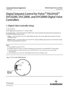
7 Refer to the DVC6200 Series quick start guide for connection CalibrationA pushbutton near the wiring terminals in the terminal box provides a quick means to autocalibrate the travel of theinstrument. The button must be pressed for 3 to 10 seconds. Autocalibration will move the valve through the fullrange of travel whether the Instrument Mode is In Service or Out of Service. However, if the Write Protection isProtected, this button will not be active. To abort, press the button again for 1 second. The calibration button isdisabled by Manual SupplementD103639X012 DVC6200 Digital Valve ControllerAugust 20145 Internal Jumpers And Switches (Optional)The input to the DVC6200 is determined by the Pt Pt/Multi Drop switch on the printed wiring DVC6200 also has a pair of optional Output terminals that can either function as a position transmitter or adiscrete switch.
8 Electrical configuration of the output circuit requires the proper setting of a DIP switch on theDVC6200 s printed wiring board. Additionally, the functional operation of the output circuit must be configured withthe user to the DVC6200 instruction manual for additional details on the settings of the selection +OUTPUT-X0430 WITH OPTIONAL I/O PACKAGEX0431 WITHOUT I/O PACKAGEPT-PT/MULTI-DROPSELECTIONX0432 DIP SWITCH FOR TRANSMITTER/SWITCHSELECTIONX0427PT-PT/MU LTI-DROPSELECTIONW rite ProtectionThere are two Write Protection states for the DVC6200: Not Protected or Protected.
9 Protected prevents configurationand calibration changes to the instrument. The default setting is Not Protected. Protection is controlled undersoftware control. Write Protection can be enabled remotely. However, to disable Write Protection to Not Protected,you must have physical access to the instrument. The procedure will require you to press a button inside the terminalbox when directed by the software as a security Manual SupplementD103639X012 DVC6200 Digital Valve ControllerAugust 20146 Dynamic VariablesFour Dynamic Variables are MeaningUnitsPVAnalog InputmA, %SV*Travel Setpoint%TV*PressurePSI, BAR, KPA, Kg/cm2FV*Travel%* User selectableThe SV, TV, and FV variables are user selectable via Command 51 to any of the following variables.
10 Variable selectionsare listed below:VariableUnitsTravel%Travel Setpoint%Pressure Port APSI, BAR, KPA, Kg/cm2 Pressure Port BPSI, BAR, KPA, Kg/cm2 Pressure A BPSI, BAR, KPA, Kg/cm2 Supply PressurePSI, BAR, KPA, Kg/cm2 Drive Signal%Analog InputmA, % Device VariablesThese variables represent measurements taken by the Device , are read only values, and are all in float format. Thesecan be read with Commands 9, 33, and IDMeaningUnits0 Analog InputmA, %1 Internal Temperature_C, _F2 Pressure Port APSI, BAR, KPA, Kg/cm23 Travel%4 Drive Signal%5 Pressure Port BPSI, BAR, KPA, Kg/cm26 Travel Setpoint%7 Differential Pressure (Port A Port B)PSI, BAR, KPA, Kg/cm28 Supply PressurePSI, BAR, KPA, Kg/cm29 Implied Valve Position%10 Primary Feedback (user selected, either Travel or Pressure)