Transcription of Hazardous Location Push Button Specifications Technical Data
1 Technical DataHazardous Location Push Button SpecificationsBulletin Numbers 800G, 800h , and 800 RTopicPageTopicPageSummary of Changes2 Bulletin 800G Hazardous Location Push ButtonsBulletin 800h Hazardous Location Push ButtonsSpecifications c-UL-us Models43 Specifications4 Specifications -Ex Models (ATEX/IECEx)48 Complete Assembled Stations6 Assembled Stations52 Momentary Contact Push Buttons Units7 Push Button Units55 Push Pull Units10 Selector Switch Units56 Selector Switch Units13 Pilot Lights57 Pilot Light Devices16 Plastic Enclosures (c-UL-us Models Only)57 Potentiometer Units17 Back-of-panel Components58 ordering Information for Bulletin 800h Stations17 Accessories59 Modifications and Accessories22 Legend Plates60 Approximate Dimensions and Shipping Weights30 Approximate Dimensions64 Bulletin 800R Hazardous Location Push ButtonsSpecifications37 Complete Assembled Stations39 Custom-built Stations40 Approximate Dimensions & Shipping Weights412 Rockwell Automation Publication 800-TD011F-EN-P - August 2019 Hazardous Location Push Button SpecificationsSummary of ChangesThis publication contains new and updated information as indicated in the following picPageUpdated wire gauge in Ta b l e the catalog number explanation for Assembled the catalog number explanation for Plastic Enclosures (c-UL-us Models Only).
2 57 Updated the Accessories Automation Publication 800-TD011F-EN-P - August 20193 Hazardous Location Push Button Specifications Bulletin 800 HBulletin 800h Hazardous Location Push ButtonsOur Bulletin 800h Type 7 and 9 Hazardous Location Push Buttons offer unmatched selection, excellent corrosion resistance, and choice of conduit seal-off solutions. You can order them as complete factory-assembled stations or as separate components with standard or long properly mounted in a Type 7 and 9 enclosure, Bulletin 800h Type 7 and 9 operators are designed to meet the requirements of the National Electrical Code for Class I, Divisions 1 & 2, Groups B, C, and D Hazardous Gas; Class II, Divisions 1 & 2, Groups E, F, and G Hazardous Dust; and, Class III Hazardous Fiber Locations. In addition, the single-gang shallow base, catalog number 800h -IHZX7, meets Class I, Group B requirements. This Type 7 and 9 equipment is listed by Underwriters Laboratories, Inc. Per National Electrical Code:Operator ConstructionThe Allen-Bradley line of Hazardous Location devices features copper-free (less than of 1% copper content) die-cast aluminum bushings and mounting rings, type #316 stainless steel operating shafts and an O-ring seal for added corrosion resistance.
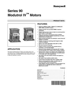
3 These components mount into a threaded hole (3/4 NPSM) in a suitable 800h Type 7 and 9 components are available in two basic formats: standard barrel (Bulletin 800h ) and long barrel (Bulletin 800HL). Standard barrel devices are suitable for mounting in panel thickness up to mm (1 in.) thick. Long barrel devices are suitable for mounting in panel thickness greater than mm (1 in.) and no thicker than mm ( in.). Both style operators offer a unique locking bracket, which provides an anti-turn feature to help prevent the operator from coming loose. The mounting rings in front of the panel are knurled to provide a second way to tighten each unit into the UseBulletin 800h Type 7 and 9 stations and enclosures are not configured for outdoor use as standard. A Type 3 rating is available, while maintaining Type 7 and 9 integrity of the enclosure, by the addition of a Type 3 sealing flange and an approved drain. The sealing flange that is shown in Figure 1 can be purchased as an option or as an accessory.
4 A Type 4 rating can be achieved by using sealing nuts to seal the push Button operators along with the sealing flange. Sealing nuts are available as accessories (see #selection).Elimination of Conduit Seal Off RequirementBulletin 800h Type 7 and 9 units can be installed with various sealing options. By using a flanged sealing well, these stations can be installed without a conduit seal off in most applications (subject to applicable codes and laws). The sealing wells that are shown in Figure 1 can be purchased as an option or as an accessory. Sealing wells have an integral Type 3 flange seal for outdoor applications. Sealed switch contact blocks are another way to help eliminate the need for conduit seal fittings in most applications (subject to applicable codes and laws). Sealed switch contact blocks can be purchased as an option on assembled stations by changing the Bulletin No. from 800h to 800R. Sealed switch contact blocks can be ordered as an accessory (see #selection). A push Button station with a sealed switch contact block is shown in Figure 1 - Sealing OptionsZoneDescription1In Class I, Zone 1 locations, all wiring methods that are permitted for Class I, Division 1 locations and Class I, Zone 0 or Zone 1 locations, including requirements for sealing, shall be permitted.
5 2In Class I, Zone 2 locations, all wiring methods that are permitted for Class I, Division 2, Class I, Division 1 or Division 2, and Class I, Zone 0 or Zone 1 locations, including requirements for sealing, shall be p e 3 Fl a n g e S e a lSealing WellsSealed SwitchContact Blocks4 Rockwell Automation Publication 800-TD011F-EN-P - August 2019 Hazardous Location Push Button Specifications Bulletin 800 HSpecificationsTable 1 - Electrical RatingsTable 2 - Mechanical RatingsTable 3 - EnvironmentalATTENTION: Performance data that is given in this publication is provided only as a guide for you to determine suitability and does not constitute a performance warranty of any kind. Such data may represent the results of accelerated testing at elevated stress levels, and you are responsible for correlating the data to actual application requirements. ALL WARRANTIES AS TO ACTUAL PERFORMANCE, WHETHER EXPRESS OR IMPLIED, ARE EXPRESSLY RatingsSee the contact ratings on page Strength2200V for 1 minute, 1300V for 1 minute (Logic Reed)Electrical Design Lifecycles1,000,000 at max rated load, 200,000 at max rated load (Logic Reed) Hz mm displacement (peak-to-peak) max/10 G max (except Logic Reed)Shock1/2 cycle sine-wave for 11 ms 25 G (contact fragility) and no damage at 100 GDegree of ProtectionType 7 and 9 Explosion Proof (Type 3 and Type 4 ratings available with accessories)Mechanical Design LifecyclesPush Buttons250,000 minPotentiometers100,000 minAll other devices200,000 minContact OperationShallow and mini contact blocks: slow double make and breakLogic Reed and sealed switch contact blocks: snap actionWire Gauge/Terminal Screw Torque# lb inTypical Operating ForcesOperators without contact blocks.
6 Flush, extended, standard mushroom, jumbo lb maxJumbo and extended aluminum mushroom lb maxMaintained selector in lb maxSpring-return Selector Switches5 in lb to stop, in lb to returnIlluminated Push Buttons and Push-to-test Pilot lb max2-position Push-Pull9 lb max push or pull3-position Push-Pull12 lb max push to in position or pull to center position(15 lb max pull to out position)Contact Blocks800T-XA1 lbLogic Reed1 lb maxSealed Switch3 lb max at in. plunger travelStackable Sealed Switch1 lb maxTemperature Range (1)(1)Operating temperatures below freezing are based on the absence of freezing moisture and +55 C ( +13 F) +85 C ( +185 F)Humidity50% at 40 C (104 F)Rockwell Automation Publication 800-TD011F-EN-P - August 20195 Hazardous Location Push Button Specifications Bulletin 800 HStandard Contact RatingsMaximum thermal continuous current Ith 10 A A DC. Ta b l e 4 shows the ratings for Bulletin 800h Type 7 & 9 units with catalog number 800T-XA 4 - Standard Contact RatingsSealed Switch Contact RatingsMaximum continuous current Ith 5 5 - Sealed Switch Contact RatingsStackable Sealed Switch Contact RatingsMaximum continuous current Ith 3 A.
7 Bulletin 800T units have control circuit ratings with sealed switch contact blocks as shown in Ta b l e 6 - Stackable Sealed Switch Contact RatingsLogic Reed Contact RatingsMaximum: 150V AC, A, 8VA and 30V DC, A, only with resistive (Low Voltage) Contact RatingsMinimum DC: 5V, 1 mAMaximum thermal continuous current Ith A A b l e 7 shows the ratings for Bulletin 800h units with catalog number 800T-XAV 7 - PenTUFF (Low Voltage) Contact RatingsStandards ComplianceCertificationsEnclosures: UL Listed (File No. E71673 Guide No. NNNY) CSA (File No. LR11924)Devices: UL Listed (File No. E10314 Guide No. NOIV) CSA (File No. LR11924)Max OperationalVolts UeUtilization CategoryRated Operational CurrentsIECNEMAV olts UeMakeBreakAC (1)(1)For applications below 24V and 24 mA, PenTUFF , Logic Reed, or stackable sealed switch contacts are A10 ADC (1) AMax OperationalVolts UeUtilization CategoryRated Operational CurrentsIECNEMAV olts UeMakeBreakAC A3 ADC AMax OperationalVolts UeUtilization CategoryRated Operational CurrentsIECNEMAV olts UeMakeBreakAC ADC AMax OperationalVolts UeUtilization CategoryRated Operational CurrentsIECNEMAV olts UeMakeBreakAC ADC A UL508 UL698 UL1203 UL1604 CSA No.
8 14 CSA No. 25 CSA No. 306 Rockwell Automation Publication 800-TD011F-EN-P - August 2019 Hazardous Location Push Button Specifications Bulletin 800 HComplete Assembled StationsIMPORTANTS upplied with mm (3/4 in.) dead end conduit entry (Cat. No. 800h -1 HZX7)OperatorContact SymbolContact ActionLegend MarkingLever Type ActuatorComponent Type ButtonsCat. No. (1) (2)(1)Operators have integral padlocking attachment.(2)Supplied with standard shallow contact blocks. For stations with sealed switch contacts, change Bulletin number from 800h to 800R. A deep enclosure is No. (2) (3)(3)STOP is extended red, START is flush green, all others are flush No. 800h -1HA7 One Push Button1 Legends800H-1HX7800H-1HX7 PCat. No. 800h -2HA7 PTwo P u s h Buttons1 ButtonMomentarySTARTSTOP800H-2HA7800H-2H A7 PFORREV800H-2HB7800H-2HB7 PRAISELOWER800H-2HD7800H-2HD7 POPENCLOSE800H-2HF7800H-2HF7 PNo Legends800H-2HX7800H-2HX7 PCat. No. 800h -2 HAM72-position Selector Switch1 MaintainedSTARTSTOP800H-2 HAM7 ONOFF 800h -2 HCM7800H-R2HC7 OPENCLOSE800H-2 HGM7800H-R2HG7 RUNSTOP800H-2 HJM7 HANDAUTO800H-2 HLM7800H-R2HA7No Legends800H-2 HXM7800H-R2HX7 Cat.
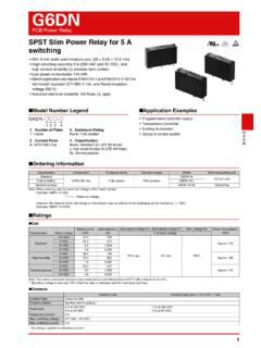
9 No. 800h -R3HA7 3-position Selector Switch1 HAND OFF AUTO 800h -R3HA7No Legends 800h -R3HX7 Cat. No. 800h -2 HAD10R7 One Pilot Light, Dual Push Buttons120V AC/DCFull STARTSTOP 800h -2 HAD10R71 other than listed - consult your local Allen-Bradley distributor 800h -2 HXD10R7 Rockwell Automation Publication 800-TD011F-EN-P - August 20197 Hazardous Location Push Button Specifications Bulletin 800 HMomentary Contact Push Buttons UnitsNon-illuminated Momentary Contact Push Button Units800H AP1 AabcdeabcBarrel TypeOperator TypeColor CapCodeDescriptionCodeDescriptionCodeDes criptionHStandard barrelAPFlush headBlankUsed only when operator type Code DPX (Table b) is orderedHLLong barrelBPExtended headDPMushroom head1 GreenDPXM ushroom head (less color cap)2 Black3 Orange4 Gray6 Red7 Blue9 Yellowdee, continuedSpecial Mushroom Head(1)(1)Special mushroom head options only apply to mushroom head operator type code DP (Table b).Contact Blocks (2)(2)For sealed switch and Logic Reed contact blocks, consult your local Rockwell Automation sales office or Allen-Bradley Blocks (2)CodeDescriptionCodeDescriptionCodeDes criptionBlankNo special headStandardPenTUFF (Low Voltage)JJumbo mushroom head plasticBlankNo contactsD1V1 mushroom head metalD11 - 1 (Mini)BV2 - 2 (Mini)HV3 - 3 - 4 - 1 - 2 - 3 - 4 Head UnitCat.
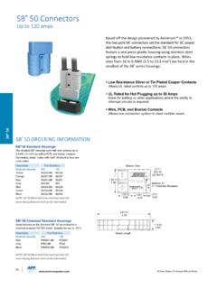
10 No. 800h -AP1 AExtended Head UnitCat. No. 800h -BP6 BMushroom Head UnitCat. No. 800h -DP6A8 Rockwell Automation Publication 800-TD011F-EN-P - August 2019 Hazardous Location Push Button Specifications Bulletin 800 HDual Momentary Contact Push Button Units800H DPH16 AAXX64abcdefab cdBarrel TypeOperator TypeMountingButton ColorCodeDescriptionCodeDescriptionCodeD escriptionCodeDescriptionHStandard barrelDPDual push buttonHHorizontal1 Left green flush/right red extendedHLLong barrelBVertical2 Left black flush/right black flushefContact Blocks (1)(1)For sealed switch and Logic Reed contact blocks, consult your local Rockwell Automation sales office or Allen-Bradley (1)CodeContact ArrangementCodeContact ArrangementLeft Button (horizontal)Top Button (vertical)Right Button (horizontal)Bottom Button (vertical)Left Button (horizontal)Top Button (vertical)Right Button (horizontal)Bottom Button (vertical)AAXX 1 - 1 1 - 1 mark specifiedNo mark specifiedAAAA2 - 2 - 2 (2)(2)To order with special marking, please specify.