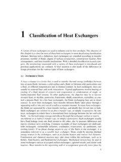
Transcription of Heat Exchangers
1 Dr. YA Hussain 66 heat Exchangers heat Exchangers are used to transfer heat between two sources. The exchange can take place between a process stream and a utility stream (cold water, pressurized steam, etc), a process stream and a power source (electric heat ), or between two process streams resulting in energy integration and reduction of external heat sources. Typically, a heat exchanger is used with two process streams. However, mutlistream heat Exchangers are sometimes used with energy extensive processes, such as LNG processing, to reduce capital cost. The term heat exchanger applies to all equipment used to transfer heat between two streams. However, the term is commonly used to equipment in which two process streams exchange heat with each other.
2 In the other hand, the term heater or cooler is used when the exchange occurs between a process stream and a plant service stream. Other terms used to describe heating equipment include: vaporizer and reboiler (for vaporization) and evaporator (for stream concentration). Exchangers can also be classified as fired ( heat source is fuel combustion) and unfired Exchangers . There are many types of heat Exchangers applied in the process industry. These types include: 1. Hairpin/Double pipe Exchangers 2. Shell and tube Exchangers 3. Plate and frame Exchangers 4. Plate-fin Exchangers 5. Spiral heat Exchangers 6. Air coolers and condensers 7. Direct contact (quenching towers) 8. Fired heaters The selection of a heat exchanger depends on many factors including capital and operating costs, fouling, corrosion tendency, pressure drop, temperature ranges, and safety issues (tolerance to leakage).
3 Different types of heat Exchangers are shown in Figure 42. In process calculations, the main objectives of heat exchanger calculations are to determine the heat duty (amount of energy to be transferred), temperature changes within the exchanger , and pressure drops. Depending on the degree of details available/needed, the calculations might be simple or thorough. For an exchanger with a hot stream and a cold stream, the heat requirements are calculated as: (11) ( ) 67 (12) ( ) Figure 42. Different types of heat Exchangers In addition, the overall heat transfer equation for the exchanger must be solved simultaneously: (13) with being the overall heat transfer coefficient, the heat transfer area, and is the log-mean temperature difference.
4 Equation (13)(13) is used when simple counter or co-current flows exist. If the flow pattern is more complex (such as the case with most shell and tube heat Exchangers ), then a correction factor ( ) term is used and the equation becomes: (14) Depending on the complexity of the chosen model, the information needed in Equation (14) may vary from rough estimation to calculation based on the exchanger geometry. 8 R. K. Sinnott, John Metcalfe Coulson, and John Francis Richardson, Coulson & Richardson's Chemical engineering Design, vol. 6, 4th ed. (Butterworth-Heinemann, 2005). 9 Warren McCabe, Julian Smith, and Peter Harriott, Unit Operations of Chemical Engineering (7th edition, 7th ed.)
5 (McGraw-Hill Science/Engineering/Math, 2004). 10 Ernst Schl nder et al., eds., heat exchanger Design Handbook (Washington: Hemisphere Publishing Corporation, 1983). 11 Don Green and Robert Perry, Perry's Chemical Engineers' Handbook, Eighth Edition, 8th ed. (McGraw-Hill Professional, 2007). (a) Plat and frame exchanger8 (b) Shell and tube exchanger9 (c) Air coolers10 (d) Double pipe exchanger11 Dr. YA Hussain 68 The overall heat transfer coefficient represents the ease with which heat is transferred from one medium to another. For example, when heat is being transferred from a hot fluid inside a tube to a cold fluid outside of the tube (as shown in Figure 2), the overall heat transfer coefficient is: (15) ( ) with being the resistance to heat transfer through each interface (hot fluid-inner tube wall, inner tube wall-outer tube wall, and outer tube wall-cold fluid).
6 The resistance calculation depends on the phase from which heat is being transferred. For example, for ( transfer at fluid-solid interface) the resistance is given by: (16) ( ) and for ( transfer through solid media), the resistance is given by: (17) ( ) All symbols here take their usual definition. As you can see from Equations (15) to (17), calculating requires knowledge of the geometry, materials properties, and flow conditions. Geometry is also needed to calculate the heat transfer area ( ). Material and flow information are needed to calculate the heat transfer coefficients ( and ). For example, the heat transfer coefficient in the fluid can be calculated from general correlations according to fluid flow pattern and phases present.
7 For example, for turbulent flow the heat transfer coefficient can be calculated using the general correlation: (18) ( ) 12 Yunus A. engel, heat transfer : A Practical Approach, 2nd ed. (McGraw-Hill, 2002). Figure 43. heat transfer through 69 Here is the Reynolds number ( ) and is the Prandtl number ( ). The parameters , , , and are constants and depend on the flow. In addition to affecting flow, the geometry of the exchanger is necessary to calculate the heat transfer area. The area is calculated based on specifications of the dimensions of process streams contact area. For example, in a shell and tube exchanger , the pipe diameter and length are used for this purpose.
8 The correction factor is used in conjunction with the LMTD to account for the deviation from the ideal counter-current flow pattern. For example, shell and tube Exchangers where the tubes make more than one pass or when two or more shells are used, as shown in Figure 44. Notice that in Figure 44(b) and (c), part of the flow resembles co-current flow rather than counter current. This flow pattern will cause a reduction in the driving force between the streams reducing the amount of heat that can be transferred. The LMTD represents the driving force between process streams and is given by: (19) ( ) where and are the temperature differences between the two fluids at the two ends (inlet and outlet).
9 The use of the LMTD represents an averaging of the driving force since the temperature difference between the two streams changes as it flows through the exchanger , as shown in Figure 45. The terms in Equation (19) represents the differences at the two ends of the plots in Figure 45. In the counter current flow, the driving force is almost constant; while in the counter current decreases as the fluids exchange heat . It is important to remember that it is not feasible for the two curves to cross or reach a pinch point. If the curves cross this means that heat transfer will switch direction which is physically impossible (the best that can happen is for both streams to reach the same temperature).
10 (a) Counter current flow (b) One shell-pass, two tube-pass (c) Two shell-passes, four tube-passes. Figure 44. Different heat Exchangers flow patterns. Dr. YA Hussain 70 The LMTD can be problematic in cases where = or when either of the temperature differences is zero. While such cases are physically feasible, numerical calculations of Equation (19) are not possible. In such cases, other averaging techniques can be applied. For example, the arithmetic mean is given by: (20) can give good approximation of when the ratios are closer to 1 but deviates largely as the ratio departs from 1. As mentioned earlier, the correction factor is used to correct the LMTD from the ideal counter current flow.