Transcription of HEAT PUMP OUTDOOR UNITS HP24 SERIES HP24 ...
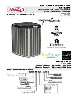
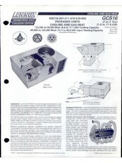
1 ENGINEERING DATAHEAT PUMP OUTDOOR UNITSB ulletin No. 480187 April 1992HP24HP24 SERIESHEAT PUMP OUTDOOR UNITSRFC III or EXPANSION VALVE to SEER*12,000 to 62,000 Btuh Cooling Capacity*11,500 to 60,500 Btuh Heating Capacity*ARI Standard 210/241 Certified RatingsTypical ApplicationFEA TURESA pplication HP24 SERIES heat pump OUTDOOR UNITS consist of eightmodels ranging from 1 to 5 tons. UNITS have SEER's up to with acooling capacity range of 12,000 to 62,000 Btuh and COP of up to heating capacity range of 11,500 to 60,500 Btuh. UNITS are designedfor use with remotely located indoor blower coil UNITS or indoor add on coilsin Fuelmaster+ applications.
2 OUTDOOR UNITS may be installed on a slabat grade level or on a rooftop. A variety of matching up flo, down flo or hor izontal indoor blower coil UNITS , with optional supplemental electric heatprovide selective sizing and installation versatility. For Fuelmaster+ con trols information, see bulletin indexed in this tab section. For completedata on indoor blower coil UNITS and Fuelmaster+ coils, see tab section,Coils Blower Coil UNITS . HP24 UNITS are test operated at the factory toinsure proper operation and are shipped ready for installation. Installer hasonly to locate unit and make refrigerant line and electrical connections tocomplete the Control Choice A choice of refrigerant flow controlsis available.
3 Use an RFC III refrigerant metering orifice for an eco nomical installation restricted to specific indoor blower coil UNITS (CB19/CBH19) or select an optional check and expansion valve kit fora larger selection of indoor IS PROVIDEDIN CONNECTOR TO PROTECTORIFICE FROM FOREIGN MAT TERCB19/CBH19 UNITDISTRIBUTORCONNECTORRFCIII METERING ORIFICE(Remove For Expansion Valve Systems)LIQUIDLINERFCIII SYSTEMS ONLYR efrigerant Flow Control III HP24 UNITS are applicable to LennoxRFC III systems when matched with CB19 and CBH19 blower coilunits only. RFCIII (Refrigerant Flow Control) is a very accurate meansof metering refrigerant in a system. Metering control is accomplishedby the exact sizing of the refrigerant metering orifice located in the dis tributor on the CB19/CBH19 coils.
4 The distributor is equipped with aflare fitting connector for easy connection of the liquid line, see illustra tion. Design of the bullet shaped orifice allows for reverse flow duringthe heating cycle. As the refrigerant flows in the reverse direction theorifice moves back to a free flow position, eliminating the need for acheck valve and related piping. The entire principle of the RFCIII sys tem involves the matching of the indoor coil and the proper sizing ofthe metering orifice. The RFCIII system equalizes pressures instantlyafter the compressor stops, eliminating the need for any extra controlsand allowing the compressor to start UNITS have been tested with matching indoor UNITS inthe Lennox Research Laboratory environmental test room and ratedaccording to Department of Energy (DOE) test procedures andin accordance with ARI Standard 210/240 89.
5 UNITS have been soundrated in the Lennox reverberant sound test room in accordance withARI Standard 270 84. UNITS and components within are bonded forgrounding to meet safety standards for servicing required by UNITS are also Warranty Compressor has a limited warranty for fiveyears. All other components have a limited warranty for one year. Re fer to the Lennox Equipment Limited Warranty certificate included withthe unit for Resistant Cabinet and Base Section Heavy gauge galva nized steel cabinet and base section are subjected to a five station metalwash process prior to a finish coat application of baked on OUTDOOR enam el. Attractive enamel finish provides the cabinet and base section withlong lasting protection from rust and corrosion.
6 Drainage holes are pro vided in the base section for moisture removal. High density polyethylenebase supports raise the unit off of the mounting surface away from dam aging Specifications, Ratings and Dimensions subject to change without notice. 1992 Lennox Industries (Continued)Accessible Control Box Conveniently located for easy access. Allcontrols are pre wired at the Tube/Enhanced Fin Coil Lennox designed and fabri cated coil is constructed of precisely spaced ripple edged aluminumfins machine fitted to seamless copper tubes. Four sided wrap around coil configuration provides extra large surface area with lowair resistance.
7 Lanced fins provide maximum exposure of the fin sur face to air stream resulting in excellent heat transfer. Fins areequipped with collars that grip the tubing for maximum contact circuiting provides uniform refrigerant distribution for high effi ciency. Flared shoulder tubing connections and silver soldering resultin tight, leakproof joints. Long life copper tubing is corrosion resistantand easy to field service. Coil is factory tested under high pressure toinsure leakproof construction. Entire coil is accessible for resistant PVC (polyvinyl chloride) coated steel wire con denser coil guard is furnished as and Quiet Compressor Compressor is hermeticallysealed and provides trouble free operation and long service life.
8 Built in protection devices assure protection from excessive current andtemperatures. Refrigerant cooled and overload protected. HP24 141is equipped with a rotary compressor. HP24 211 thru HP24 650 mod els are furnished with a crankcase heater as standard equipment toensure proper compressor lubrication at all times. Heater is tempera ture actuated to operate only when required. The compressor compo nents are spring mounted within the sealed housing. In addition, thecompressor is installed in the unit on resilient rubber mounts for quietand vibration free operation. Muffler, factory installed in discharge line,reduces operating sound Line Accumulator Factory installed and piped accumula tor is furnished on HP24 141, 460, 510 and 650 models only.
9 Accu mulator prevents large amounts of liquid refrigerant from entering thecompressor eliminating damage on start ups and refrigerant Valve Factory installed 4 way reversing valve providesa rapid change in refrigerant flow direction resulting in quick change over from cooling to heating and vice versa. Valve operates on pres sure differential between OUTDOOR unit and indoor Valve Designed and sized specifically for use in heatpump system. Sensing bulb is located on the suction line between thereversing valve and compressor to sense suction temperature in anycycle. Factory installed and Control Solid state time/temperature defrost control is fur nished as standard equipment.
10 Control initiates a defrost cycle every30, 60 or 90 minutes of compressor on" time at OUTDOOR temperaturesbelow 35 F (factory setting 60 minutes). Maximum defrost cycle is 14minutes. Defrost thermostat mounted on the liquid line determineswhen a defrost cycle is required and when to terminate a Controls Factory installed start capacitor and potential relayprovides assistance for compressor start under loaded conditions,low voltage or low ambient Condenser Fan Efficient direct drive fan moves large airvolumes uniformly through the entire OUTDOOR coil resulting in high re frigerant capacity. Vertical discharge of air minimizes operatingsounds and eliminates hot air damage to lawn and shrubs.