Transcription of Heat Pump Wiring Diagrams - Alpine Home Air
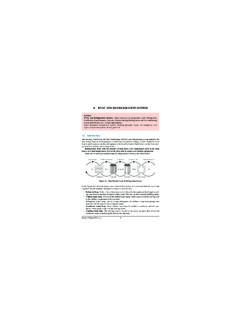
1 1(800) Heat Pump with Single Stage Gas Furnace and All Fuel Kit Control Wiring Heat PumpStandard Thermostat Standard FurnaceOutdoor Heat Pump Thermostat 24 Volt+ Fan Only Operation Air Conditioning Common1st Stage Backup HeatAC Reversing ValveControl BoardLow Voltage ConnectionAll Fuel KitThermostat Furnace Condenser9 Some AC Systems will have a blue wire with a pink stripe in place of the yellow or Y wire. This diagram is to be used as reference for the low voltage control Wiring of your heating and AC system . Always refer to your thermostat or equipment installation guides to verify proper Wiring . NOTEOOOOOO1231(800) Heat Pump with Single Stage Gas Furnace and Honeywell VisionPro 8000 as All Fuel Kit Control WiringHeat PumpHoneywell VisionPro 8000 Standard Furnace24 Volt+ Fan Only Operation Air Conditioning 1st Stage Gas HeatAC Reversing ValveCommonOutdoor Temp Sensor Outdoor Temp Sensor Control BoardLow Voltage Connection10 Some AC Systems will have a blue wire with a pink stripe in place of the yellow or Y wire.
2 This diagram is to be used as reference for the low voltage control Wiring of your heating and AC system . Always refer to your thermostat or equipment installation guides to verify proper Wiring . NOTES*Vision Pro 8000 works with wired or wireless outdoor temp *To Outdoor Temp SensorAUX/EAUX/EFactory JumperWire Size: 18 Gage1(800) Heat Pump with Standard Air Handler and No Electric Backup HeatStandard Heat Pump Thermostat Standard Air HandlerHeat Pump Condenser 24 Volt+ Fan Only Operation CommonAir Conditioning-Heat PumpReversing Valve 1st Stage Heat (white)2nd Stage Heat (brown)Low Voltage Connection11 Some AC Systems will have a blue wire with a pink stripe in place of the yellow or Y wire.
3 This diagram is to be used as reference for the low voltage control Wiring of your heating and AC system . Always refer to your thermostat or equipment installation guides to verify proper Wiring . NOTEOOOWire Size: 18 Gage1(800) Heat Pump with Standard Air Handler and Single Stage Electric Backup HeatStandard Heat Pump Thermostat Heat Pump Condenser 24 Volt+ Fan Only Operation CommonAir Conditioning-Heat PumpReversing ValveElectric Backup HeatLow Voltage Connection12 Some AC Systems will have a blue wire with a pink stripe in place of the yellow or Y wire. This diagram is to be used as reference for the low voltage control Wiring of your heating and AC system .
4 Always refer to your thermostat or equipment installation guides to verify proper Wiring . NOTEOOOS tandard Air HandlerAUX/EWire Size: 18 Gage1(800) Heat Pump with Standard Air Handler and Two Stage Electric Backup HeatStandard Heat Pump Thermostat Standard Air HandlerHeat Pump Condenser 24 Volt+ Fan Only Operation CommonAir Conditioning-Heat PumpReversing Valve1st Stage Heat GasElectric Backup Heat Low Voltage Connection13 Some AC Systems will have a blue wire with a pink stripe in place of the yellow or Y wire. This diagram is to be used as reference for the low voltage control Wiring of your heating and AC system . Always refer to your thermostat or equipment installation guides to verify proper Wiring .
5 NOTEOOOTied togetherAUX/EAUX/EWire Size: 18 Gage1(800) Heat Pump with Variable Speed Air Handler Without Electric Backup Heat Control WiringStandard Heat Pump Thermostat Variable Speed Air HandlerHeat Pump Condenser Low Voltage Connection14 Some AC Systems will have a blue wire with a pink stripe in place of the yellow or Y wire. This diagram is to be used as reference for the low voltage control Wiring of your heating and AC system . Always refer to your thermostat or equipment installation guides to verify proper Wiring . NOTEOOOAUX/E24 Volt+ Fan Only Operation CommonAir Conditioning-Heat PumpReversing Valve1st Stage Heat GasElectric Backup Heat OAUX/EY1W1 Wire Size: 18 Gage1(800) Heat Pump with Variable Speed Air Handler and Single Stage Electric Backup Heat Control Wiring15 Some AC Systems will have a blue wire with a pink stripe in place of the yellow or Y wire.
6 This diagram is to be used as reference for the low voltage control Wiring of your heating and AC system . Always refer to your thermostat or equipment installation guides to verify proper Wiring . NOTE24 Volt+ Fan Only Operation CommonAir Conditioning-Heat PumpReversing Valve1st Stage Heat GasElectric Backup Heat OAUX/ESingle Stage Heat Pump Thermostat Variable Speed Air HandlerHeat Pump Condenser Low Voltage ConnectionOOOAUX/ETied togetherY1Y2W1 Wire Size: 18 Gage1(800) Heat Pump with Variable Speed Air Handler and Two Stage Electrical Backup Heat Control Wiring16 Some AC Systems will have a blue wire with a pink stripe in place of the yellow or Y wire.
7 This diagram is to be used as reference for the low voltage control Wiring of your heating and AC system . Always refer to your thermostat or equipment installation guides to verify proper Wiring . NOTE24 Volt+ Fan Only Operation CommonAir Conditioning-Heat PumpReversing Valve1st Stage Heat GasElectric Backup Heat OAUX/EStandard Heat Pump Thermostat Variable Speed Air HandlerHeat Pump Condenser Low Voltage ConnectionOOOAUX/EW1Y1