Transcription of HEAVY DUTY INCLINED VIBRATING SCREENS - …
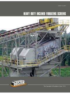
1 HEAVY duty INCLINED VIBRATING SCREENSThe Standard of Excellence Since No. 300-DDEISTER HEAVY duty INCLINED VIBRATING SCREENSNote: Throughout this bulletin, many of the products have belt and flywheel guards removed to show the drivesWith rising production costs, more rigid specifications andstiffer competition, it takes the best screening equipment tomeet the challenge big capacity, cost cutting, hard workingDeister SCREENS of the proper size and type, and designedspecifically to fit your application. Whatever the specificationor material type, Deister engineers will find the right solutionfor built and requiring minimal maintenance, Deister SCREENS deliver unmatched precision performance day afterday and year after year. Extra protectionis provided at allvital points, and quantity-controlled oil lubrication ensures long bearing life and dependable production even under adverse operating conditions, or when handling the most abrasive material , Deister SCREENS are backed by a follow-through parts and service policy without equal for Deister top management is personally interested in the continued profitable operation of every Deister VIBRATING SCREENS have many outstanding features which are standard on each unit.
2 TYPE HT AND BHT SIZES UP TO AND INCLUDING 16' MODELSBelt Guard Removedto Show DriveFeed Box withReplaceable A-R LinerUnitized VibratingMechanismRubber Torsion PivotMotor BaseFlywheel with StrokeAdjustment PlatesOverhead MotorPlatformInterchangeableScreen Panels andTension PlatesAdjustable PanelHeavy H-BeamStationary BasePick-up Bracket andCable Suspension LugSnubber (Friction Checks)Access PortHeavy-DutyTensionAssemblyAdjustable Trunnion MountDischarge lips onall decks included as standard; alsoavailable withreplaceable steel or rubber linerTYPE BHT-36163 Deck 6' x 16'2 TYPE HM AND BHMR einforcing PlateOptional Rubber LinerInterchangeableScreen Panels andTension PlatesOptional Center Hold-Down for HEAVY Wire ClothDischarge lips on all decksincluded as standard; alsoavailable with replaceable steel or rubber liner as shownExplanation of Model LettersBH-Beam BaseHHeavy duty InclinedTTo p M o u n t e d V i b r a t i n gMechanismMMiddle VibratingMechanismCSCable Suspended UnitXHExtra HeavyPPortable Plant TypeExplanation of Model NumbersFIRSTN umberNUMBERof DecksSECONDW idthNUMBERin FeetTHIRD &LengthFOURTHin FeetNUMBERSE xample: BHM-3820H-Beam Base; INCLINED ; MiddleVibrating Mechanism.
3 ThreeDecks, 8' wide x 20' Equipment Oil lubricated VIBRATING mechanism Steel coil spring suspension system Snubbers (friction checks) Pick-up brackets and cable suspension lugs Automatic spring-tension screen cloth tensioning device Tension plates of exclusive design Interchangeable screen panels Bolted construction for easy replacement of wear parts Access ports Discharge lips Removable back plates, or rubber flaps, completely seal feed end Adjustable throw Sideplates reinforced with 5 8" x 31 2" verticalbraces (5 16" thick sideplates standard on 3', 4' & 5' wide models; 3 8" thick side platesstandard on 6', 7', 8' & 10' wide models)Optional Equipment Wide-flange H-beam base Feed box Oil filtration system Spring covers Snubber guards Motor mount, V-belt drive, and guard Spray pipe holes Spray pipe equipment Turbo washer troughs Horizontal sub-base Dust enclosure Ball tray decks Heated decks Extra HEAVY duty (XH) Models Rubber coating on exposed surfaces Tension wedges for screen cloth tensioning Rubber splash curtain A-R steel, rubber or urethane wear liners Rubber- or urethane-covered tension plates Manganese and A-R steel wear plates for tension platesOil Level GaugeUsed on most unitswith mechanismbetween Type Spring Support SystemAccess Port Cover PlateFeed Box With ReplaceableRubber LinerFlywheel With Stroke Adjustment PlateVibrating MechanismV-Belts & Motor Sheave, Belt Guard Removed to Show DriveRubber Torsion Pivot Motor BaseHeavy- duty Tension AssemblySnubber (Friction ChecksTYPE BXHM-36163 Deck 6' x 16'3 DEISTER UNITIZED LONG-LIFE VIBRATING MECHANISMS lingermist LubricationDeister s exclusive slingermistlubricating system makes it possible for Deister SCREENS to operate at higher speeds and at lower operating temperatures.)
4 This system is the ultimate in oil lubricationof anti-friction bearings and assures safe operating temperatures under extremelyhot climatic conditions where it, in effect, acts as an oil cooling outstanding feature of theTy p e TDeister VIBRATING screen is the exclusive unitized VIBRATING mechanism mountedon top of the VIBRATING entire VIBRATING mechanism is a precision constructed, jig assembled unit,which incorporates all the advantages ofa two-bearing VIBRATING mechanism andruns in a bath of oil with internal andexternal labyrinth seals to prevent loss of oil and entrance of lower portion of the shaft casingtube serves as the oil reservoir across its entire length. The oil is agitated byslingers on the eccentric shaft and constantly envelops the spherical rollerbearings and all moving parts. It shouldnever be necessary to add oil to themechanism, with only periodic oilchanges recommended. Renewablesleeves between the inner race of thebearing and the shaft prevent wear onthe shaft.
5 Should wear on the sleeveoccur, even after years of rugged service,the original close factory tolerances can be easily restored by the simplereplacement of the renewable 1926, Deister has always designedits VIBRATING mechanisms with the bearinga slip fit on the replaceable sleeve, and apress fit in the housing. The replaceablesleeve is a slip fit on the shaft. Slip fitsassure more even wear on the bearingsand sleeves providing longer life andeasier VIBRATING mechanism is demountableand readily interchangeable. Where anumber of the same size SCREENS are inoperation, the unitized mechanism can be unbolted and attached to anotherframe without disturbing any of the internal clearances of the shaft and bearings. The large diameter shaft casingtube, welded or bolted to 5 8", 3 4", o r 1 "thick housing plates, maintains properalignment of the entire (throw) adjustments can be made in the field by simply adding or removing counter-weight plates to/from the unbalanced fly M VIBRATING MechanismThe VIBRATING mechanism is locatedbetween the decks on all Ty p e Munits, regardless of size.
6 Since it is not economically feasible nor practical from an engineering standpoint, thevibrating mechanism is located betweendecks on all units longer than 16' or onmost units that are 7', 8', or 10' VIBRATING mechanism mountedbetween decks incorporates all the features of the Type T top-mountedmechanism, with the exception of the unitized feature. The steel tube shaftcasing is protected by the standard 3 8"thick steel-backed rubber tack-welded to the tube, or a replaceable steel shieldor thicker rubber when Ty p e Mmechanism produces a uniform true circle movement of thevibrating frame and screening VIBRATING mechanisms are standard on 2 and 3 deck, 8' x 20'; and on 2 deck, 8' x 24' SCREENS . Tr i p l e v i b r a t i n g m e c h a n i s m s a re s t a n d a rd o n 3 d e c k 8 ' x 2 4 ' and larger units. The two shafts of the dual mechanism are each individually motor driven while the triple mechanism is driven on the feed end and discharge end shafts.
7 Timing belts on the dual and triple mechanisms prevent any non-synchronous OPPOSED ELLIPTICAL THROWTheTy p e TVibrating SCREENS featureDeister s powerful positive opposed elliptical throw action, which permits the SCREENS to be operated at a flatterscreening angle by controlling the movement of material on the screen for the greatest speed and efficiency insizing. Note from the diagram below that the path of travel at any point onthe surface of the screen cloth nearer the feed end takes the form of an ellipsewhich revolves and leans toward the discharge end of the screen . As the discharge end is approached and the surface of the cloth takes a steeperslope, this elliptical path, while revolvingin the same direction as before, leansback toward the feed end of the small arrows alongside the ellipseshow graphically the accelerating or forward conveying motion on the flattersections of the screen and the retardingeffect, or backward thrust, of the sameforce on the steeper f u r t h e r i m p r o v e t h e e f f i c i e n c y o fDeister Ty p e TScreens, adjustable slopepanels are provided as standard equip-ment with the unit.
8 This feature permitsthe slope of the screen cloth panels to beindependently adjusted at both the feedand discharge ends in order to increaseor decrease the screening angle. If it isdesirable to accelerate the movement ofthe feed coming onto the screen in orderto thin out the bed and provide evenquicker stratification, the adjustable panelpermits the required increase of slope. Ifit has been found that at the dischargeend of the screen , where the bed hasthinned out, that the particles have a ten-dency to pass over the screen a little toorapidly, travel at the discharge end can beslowed or retarded by decreasing theslope of the end PortsAccess Ports (hand-holes) areprovided on multiple deckunits to permit removal andreplacement of any onescreening surface withoutdisturbing the other decksand eliminating the necessityof a person or personsbetween decks when hold-downs are not used. Theseports with doors removed,also provide the operatoreasy inspection of thescreening surface to checkdeck wear, possible blindingor plugging, depth of bed, or any matters connectedwith the operation of thatparticular oval-ended rectangularopenings, 5"x 10", are rein-forced with 5 8"-thick 7"x 13"steel frames welded to thesideplates.
9 Easily removedplates cover the bed at input andis quickly stratified andmoved forward rapidlyto spread HEAVY section hasvigorous circularthrow for accuratesizing of thinned action to retainnear size material for maximum spring tensionDECK SURFACE TENSION SYSTEMSF igure 1:Standard automatic spring tension assembly for 3', 4', 5' & 6' wide models. Powerful coil tension springs and tension plates hold the screen cloth over a series of support bars arranged in an arc. Support spacing is governed by size ofopening and shape of screeningmedia. As the screen cloth wirewears thin or becomes stretched, the springs automatically keepthe cloth in constant tension, thereby preventing the whippingor flexing of the cloth that causes wire breakage. The side opposite the spring is held by a half-sphere cast iron nut withindentations fitting the lugs on the steel casting welded to thesideplate, which prevent the nut from backing angles are formed to 94 to provide the correct interlocking fit between tension plate, screen cloth hook strip,and the supporting ledge angle to prevent the pinching or rocking-up of the screen cloth in the hook-strip area, whichcauses premature tension assemblies are required due to the stronger curved tension plates.
10 The method shown in Figure 1 is recommended for medium and fine screen cloth or lightweightperforated assemblies (Figures 1 through 7) are interchangeable, as holes and castings in sideplates are identically 2:Standard HEAVY duty tension assembly for HEAVY wire cloth or perforated plate with hook 3:Optional tension wedge assembly interchangeablewith all assemblies (Figures 1 7) by substitution of forged slotted bolt, spherical washer, and wedge, using the same holesand steel casting in sideplate as above, with same tension 4:Optional tension wedge and rubber spring assemblies combine advantages of both types illustrated inFigures 1 and 3; and same specs as Figure 3 with addition of rubber spring. Wedges held firmly in place by spring actionwith constant attention 5:Standard automatic spring tension assembly at bothside plates with dual center support bars and center hold 6:Standard automatic spring tension assembly for 7', 8' & 10' wide units double crown with split screen cloths downward hooks in center with molded rubber (as shown) orsteel bolted-type cover strip provides easier replacement,even flow of material over entire width of unit, better tensioningcapability giving longer screen life.