Transcription of HELICAL BEVEL GEAR UNITS HELICAL BEVEL GEARED …
1 3P0105-51 / 2004-11 HELICAL BEVEL gear UNITSHELICAL BEVEL GEARED MOTORSDIN EN ISO 9001:2000 operating instructions HELICAL BEVEL gear UNITS SK42 Important InformationIntended useGear UNITS / GEARED motors are designed for the purpose ofconverting rotary speed and torque. They are intended for use inindustrial systems and may only be used as recommended in theRexnord-Stephan technical documentation and in accordance withthe specifications on the type identification andwarningsDANGER, RISK OF ELECTRIC SHOCKO perationWarrantyCompliance with these operating instructions is the prerequisite forensuring trouble-free operation and acceptance of any warrantyclaims. Therefore, first carefully read through the operatinginstructions before working with the drive unit !
2 Start-upMaintenanceInstallationDisposalT he personnel entrusted with the handling, storage, installation,start-up, inspection and maintenance of the drive unit must bequalified for industrial, mechanical and electrical drive unit must be disposed of in compliance with currentlyapplicable parts, gearwheels, shafts, covers and flanges of the gearunits are to be disposed of as steel oil is to be disposed of in accordance with applicableenvironmental protection GmbH & Co. KG Ohsener Str. 79 83 D 31789 Tel: +49 5151 780 0 Fax: +49 5151 4453 operating instructions HELICAL BEVEL gear UNITS SK43 Table of Contents1 Principle Design, HELICAL BEVEL gear UNITS .. Design, HELICAL BEVEL GEARED Motor.
3 Design, U and I-Lantern .. Motors Type Code .. Conditions .. Power Transmission Elements .. the HELICAL BEVEL gear unit with Solid Shaft .. Coupling on Output Shaft .. Coupling on Drive Shaft to Install the Motor (I-Lantern) .. a Flange Motor with HELICAL BEVEL GEARED Motors with Hollow Shaft with Keyway .. HELICAL BEVEL GEARED Motors with Hollow Shaft with Shrink-Fit Ring .. HELICAL BEVEL GEARED Motors with Hollow Shaft with Conical Clamping 163 Start-Up .. Connection .. Oil Level and for Leaks .. Inspection .. change .. overhaul .. and Maintenance Intervals (Overview).. Preservation .. 21 operating instructions HELICAL BEVEL gear UNITS SK44 Malfunctions .. 216 Lubrication .. of Lubricants.
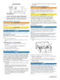
4 Filling Quantities for 3-Stage BEVEL gear Filling Quantities for 4-Stage and 5-Stage gear UNITS .. Bearing Grease, Regreasing Quantities .. Quantities for U & I-Lanterns .. Quantity for Shaft Bearing .. 247 Positions of Lubricant .. to to SK9 with Pre-Stage SI3 .. Facility for Roller Bearing Grease .. Level Glass .. Expansion Tank .. 288EG Certificate of 299 Sales and Service Branches .. 31 Notes .. 33 operating instructions HELICAL BEVEL gear UNITS SK451 Principle Design, HELICAL BEVEL gear Principle Design, HELICAL BEVEL GEARED MotorThe following illustration shows the principle design of a HELICAL BEVEL GEARED motor. It isintended as a reference aid to the individual parts lists. Variations are possibledepending on the gear unit size and foot strips5310 Output shaft5410 Pinion5420 Gearwheel5430 Pinion shaft5440 Gearwheel5450 Pinion shaft5460 Gearwheel571.
5 / 572. / ring5821 / 583. key585. / 586. / ring/shim ring588. / ring5910 / 5911 Gasket5913 / 5914 / 5915 End cover5914 End cover or protective cover for hollow shaft "H" (option)5918 Protective cover for hollow shaft "S" (option) / 596. / shaft seal5671 rotary shaft sealOperating instructions HELICAL BEVEL gear UNITS Principle Design, U and I-LanternThe following illustration shows the principle design of a U or I-lantern. It is intended as areference aid to the individual parts lists. Variations are possible depending on the gearunit size and motor fastening1671 rotary shaft seal drive shaft BA NBR0960 Screw rear frame fastening1671 rotary shaft seal drive shaft BA Viton1100 Coupling kit1675O-ring flange NBR1110 Coupling half, motor side1714 Retaining ring, pinion Z11111 Dog, flexible element1811 Feather key, drive shaft1210 Lantern/frame1813 Feather key, pinion Z11215 Screw plug1836 Spacer ring, shaft unit1220 Cover/flange/adapter1945 Shaft nut, shaft unit1300 Shaft kit1961 Screw cover/flange1510 Bush, drive shaft1970 Screw plug/breather screw1610 Bearing.
6 Drive shaft1971 Screw plug/breather screw1670 rotary shaft seal drive shaft BASLNBR1979 Lubricating nipple1670 rotary shaft seal drive shaft BASLV itonOperating instructions HELICAL BEVEL gear UNITS SK47 Drive unit No designation:integrated motor UIEC flange motor9 II-lantern Accessory for gear unit RBackstop on drive shaft(not for sizes 2 to 6 in U-version)10 Specify direction of rotation 11 Motor: Shaft arrangement LOutput shaft left ROutput shaft right12 TOutput shaft left and right13 Mounting positions Only for gear UNITS with more than 3 stages25 Size, pre-stage gear unit26 Design index, pre-stage gear unit27 Number of stages, pre-stage gear GEARED Motors Type Code S K345678910-11-1213S K345672526278910-11-1213 Output flange ZNo flange FB5 flange3 T RB14 flangeAgitator version Output shaft HHollow shaft with keyway NSolid shaft SHollow shaft with shrink-fit ring4 BHollow shaft with conical clampingsleeve Size5 2 - 3 - 4 - 5 - 6 - 7 - 8 - 9 Design index: 6 Metric version6 7 Inch versionExample.
7 S K345678910-11-1213SK housing, no flange, solid shaft, size 3, design index 6, three-stage, gear ratio i = 1/25, Rexnord integral motor size 112, shaft arrangement left, mounting position 1S K345672526278910-11-1213SK housing, B5 flange, hollow shaft with keyway, size 5, design index 6, three-stage, size pre-stagegear unit 1, design index pre-stage gear unit 6, two-stage pre-stage gear unit , total gear ratio i =1/350, U-lantern for motor size 90, shaft arrangement left, mounting position 1 Number of stages7 CThree-stage8 Total gear ratio2-stage and 3-stage gear unitsGear unit with more than 3 stagesZ N 3 6 C 25 S112 L 1F H 5 6 C 1 6 B 350 U 90 L 1 operating instructions HELICAL BEVEL gear UNITS SK48 GETRIEBEMOTORENTYPENSCHL SSELGEARED MOTORCODINGMOTO-REDUCTEURSCODIFICATION*: refer to Rexnord-Stephan*: nous consulter Rexnord-Stephan*.
8 An Rexnord-Stephan wenden2bis83 ZNHI ntegral motorMoteur int gr Integrierter MotorBrake kitKit de freinBremskitIntegral brake motorMoteur-frein int gr Integrierter Bremsmo-torU (+R)IEC - CEII (+R)Mounting positionsPositions de montageEinbaulagenShaft arrangementDisposition des arbresWellenanordnung12 * 34 *56-F-Execution with built-onmounting pads(for sizes 2 to 5)Ex cution pattes accol es(pour tailles 2 5)Ausf hrung mitangebauten Fu leisten(f r Baugr en 2 bis 5)SBF (B5)T (B14) Backstop atintermediate shaftAntid vireur l'arbreinterm diaireR cklaufsperre an der Zwischenwelle(+R): not for sizes 2 to 6(+R): pas pour les tailles 2 6(+R): nicht f r Baugr en 2 bis 6 LRTLR Solid low speed shaftArbre petite vitesse pleinVollwelle Hollow low speed shaftArbre petite vitesse creuxHohlwelleOperating instructions HELICAL BEVEL gear UNITS SK492 General ConditionsThe drive UNITS must be installed or attached free of vibration or mounted on a flat, rigidand solid frame or foundation in order to avoid : The drive UNITS must be aligned with the utmost care!
9 Stress and strainin the housing must be align the gear unit , place it on the 3 mounting points and use shims to match theother point to an accuracy of less than the gear unit has been aligned correctly and after all the shims have been fitted, thegear unit must be firmly screwed down to the foundation. Screw class in accordancewith DIN 267. Screw size: see dimensioned drawings. The screws must be tightened tothe torque requirements as specified by the lubrication and ventilation are ensured only when the gear unit is mountedin the correct is necessary to correct the amount of lubricant and the position of the breather screw ifthe mounting position of the gear unit is to start-up, check the position dependent oil level in the drive unit by undoing the oillevel screw plug (see section 7) / at the oil inspection window on the drive 2 features lifetime lubrication.
10 In this case, the surface temperature and thenoise level emitted by the gear unit must be constantly monitored during the start-up inserts or pads made of plastic must be used if there is a risk ofelectrochemical corrosion between the gear unit and system. Connect the gear unithousing to cooling air intake of the motor must not be Mounting Power Transmission Mounting the HELICAL BEVEL gear unit with Solid ShaftFlexible couplings should be used for direct power transmission from the gear unit to thedrive machine and friction or safety couplings if there is a risk of the unit use rigid couplings in connection with unsupported or overhanging shafts ( withagitators or fan drives). Due to the radial forces produced, power transmission elementssuch as flat belts or V-belts, gearwheels and sprockets, cranks, eccentric cams etc.