Transcription of HEX BEAM
1 HEX beam By K4 KIO - Page revision date 6/2010 By PU7 IRR - Word edition date 12/2010 This file provides guidelines to build a G3 TXQ broad band hexagonal beam antenna for the six amateur radio bands, 20, 17, 15, 12, 10 and 6 meters. This antenna is featured in the March 2009 edition of QST magazine and is a significant improvement over the Hex- beam design. The hexagonal beam offers a number of features as follows: Gain and front/back comparable to a two element Yagi. Five bands with low SWR Broad band characteristics Low weight and low wind load Construction from general hardware components Ease of adjustment If you have been to other sites on construction of the hexagonal beam you might be a bit confused. You see, some sites tell you how to build the original hexagonal beam which is patterned after the design of the HEX- beam , a trademarked product of Traffie Technologies.
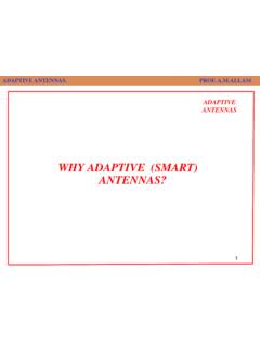
2 The wires for this original design for a single band look from above, like an M over a W . For a more full understanding of the technical parameters of the G3 TXQ broad band hexagonal beam , visit the web site of its inventor, Steve Hunt, G3 TXQ. ( ) If you feel you would rather not get into building your own G3 TXQ broad band hexagonal beam , I can build one for you. See the Hexagonal beam by K4 KIO for sale details here. ( ) Available for purchase This original design is a good antenna and owners of the HEXperformance as were builders of the homebrew version. I used to be one of the homebrew builders and was so enthusiastic that I published a set of guidelines like these to help others build o But, things have progressed a little and thanks to the exhaustive work of Steve Hunt, G3 TXQ, a slightly different configuration of the hexagonal beam has been discovered. Viewed from above the wires for a single bander look like the sketch to the righ Which one is better?
3 Well, owners of the original HEXthe market are selling only the new broad band hexagonal beam and that version of the hexagonal beam instead of the original. And here is the reason why. Overall Description This is a G3 TXQ broad band hexagonal beam for 6 and is constructed of six fiberglass tubes and 14 or 16 gauge stranded copper wire. The center post is a five foot piece of fiberglass or PVC. The beam is fed at the top of the center post with 50 ohm coax and weighs about 25 pounds. The hexagonal beam consists of two elements fo"M" and the reflector element is wrapped around the four spreaders to the rear of the driver wires. The elements are made of wire instead of tubes used by most a supporting structure. The supporting structure consists of six flexible fiberglass tubes attached to a base. The tubes are as shown and thus the name hexagonal beam . The antenna elements are held in place by the base/tube structure, the wires and cords.
4 All bands of the antenna are fed by a single coax cable. To the right are sketches of how the G3 TXQ broad band hexagonal beam is configured for a single hexagonal beam can be viewed data on the G3 TXQ BroadBand Hexagonal beam by K4 KIO Freq. bands (M): Weight: Diameter: Wind Surface Area: The support structure for the hexagonal beam resembles an umbrella upside down. To the left, wires only for a five band hexagonal beam are meters are the innermost. The gaps between the ends of wires are insulated end spacers which keep the tips of the driver wires and reflector wires at the specified distance from each other for proper coupling. The driver wires are fed with a single coax from the top with each band's driver wires connected at different vertical positions on the center post (handle of the umbrella).The spokes of the hexagonal beam are flexible tubes that keep tension on the wiresgood antenna and owners of the HEX- beam are quite vocal about its performance as were builders of the homebrew version.
5 I used to be one of the homebrew builders and was so enthusiastic that I published a set of guidelines like these to help others build oBut, things have progressed a little and thanks to the exhaustive work of Steve Hunt, G3 TXQ, a slightly different configuration of the hexagonal beam has been discovered. Viewed from above the wires for a single bander look like the sketch to the right. Which one is better? Well, owners of the original HEX- beam are very loyal. But the only competitors in the market are selling only the new broad band hexagonal beam and home brewersthat version of the hexagonal beam instead of the original. And here is the reason a G3 TXQ broad band hexagonal beam for 6 - 20 meters. It is just less than 22 feet in diameter fiberglass tubes and 14 or 16 gauge stranded copper wire. The center post is a five foot piece of fiberglass or PVC. The beam is fed at the top of the center post with 50 ohm coax The hexagonal beam consists of two elements for each band.
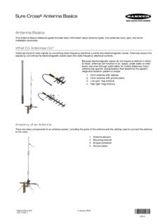
6 The driven element is in the shape of an "M" and the reflector element is wrapped around the four spreaders to the rear of the driver wires. The elements are made of wire instead of tubes used by most Yagi antennas. Therefore there is a need fa supporting structure. The supporting structure consists of six flexible fiberglass tubes attached to a base. The tubes are as shown and thus the name hexagonal beam . The antenna elements are held in place by the base/tube structure, the wires and cords. All bands of the antenna are fed by a single coax cable. To the right are sketches of how the G3 TXQ broad band hexagonal beam is configured for a single band. A sketch of the wires of a five band hexagonal beam can be viewed here. Overall data on the G3 TXQ Broad Band Hexagonal beam by K4 KIO Freq. bands (M): 6, 10, 12,15,17,20 Weight: 25 lbs Diameter: 22 ft Wind Surface Area: Sq Ft The support structure for the hexagonal beam resembles an umbrella upside down.
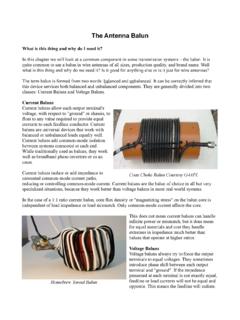
7 To the left, wires only for a five band hexagonal beam are shown. The wires for 20 meters are the outermost and 10 meters are the innermost. The gaps between the ends of wires are insulated end spacers which keep the tips of the driver wires and reflector wires at the specified distance from each other for proper The driver wires are fed with a single coax from the top with each band's driver wires connected at different vertical positions on the center post (handle of the umbrella).The spokes of the hexagonal beam are flexible tubes that keep tension on the wires while supporting their are quite vocal about its performance as were builders of the homebrew version. I used to be one of the homebrew builders and was so enthusiastic that I published a set of guidelines like these to help others build one. But, things have progressed a little and thanks to the exhaustive work of Steve Hunt, G3 TXQ, a slightly different configuration of the hexagonal beam has been discovered.
8 Viewed from above the wires for a beam are very loyal. But the only competitors in home brewers are all building that version of the hexagonal beam instead of the original. And here is the reason why. 20 meters. It is just less than 22 feet in diameter fiberglass tubes and 14 or 16 gauge stranded copper wire. The center post is a five foot piece of fiberglass or PVC. The beam is fed at the top of the center post with 50 ohm coax r each band. The driven element is in the shape of an "M" and the reflector element is wrapped around the four spreaders to the rear of the driver wires. The agi antennas. Therefore there is a need for a supporting structure. The supporting structure consists of six flexible fiberglass tubes attached to a The antenna elements are held in place by the base/tube structure, the wires and Kevlar/Dacron cords. All bands of the antenna are fed by a single coax cable. To the right are sketches of how the A sketch of the wires of a five The support structure for the hexagonal beam resembles an umbrella upside down.
9 To the left, wires wires for 20 meters are the outermost and 10 meters are the innermost. The gaps between the ends of wires are insulated end spacers which keep the tips of the driver wires and reflector wires at the specified distance from each other for proper The driver wires are fed with a single coax from the top with each band's driver wires connected at different vertical positions on the center post (handle of the umbrella).The spokes of the hexagonal while supporting their weight. Why the G3 TXQ Broad Band Hexagonal beam ? The classic hexagonal beam has been in use for several decades and a commercial version is available for purchase in a variety of configurations; multi-band, mono band, etc. Many, including the author have built home brew versions of the HEX-BEAMR and used them quite successfully. Guidelines for building one are available on other sites for those who prefer to stick with the tried and true.
10 The classic hexagonal beam , for its compact size, is fairly narrow banded in its front/back and SWR performance. This is one of the trade offs for the compact physical size that makes the classic hexagonal beam so attractive. In late 2007 Steve Hunt, G3 TXQ conducted extensive testing and modeling of many variations of the classic hexagonal beam seeking to overcome its narrow banded deficiency without sacrificing the simplicity and small size. The design featured in this G3 TXQ broad band hexagonal beam is the result of his efforts in this regard. A full explanation of the design is available on Steve's web site. An overall comparison of the new broad band design and the classic design is available. These guidelines are based on my own construction of the G3 TXQ broad band hexagonal beam . The New G3 TXQ Broad Band Hexagonal beam vs.