Transcription of HFKA HFKA-T en - hongfa.com
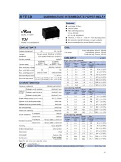
1 1 1)StableBreakMake 1)TransientBreak251025271781 10541 : Max.: 10msHFKA: -40 to 85 HFKA-T : -40 to 12510Hz to 500Hz 49m/s298m/s2 PCB 7)Plastic sealedFlux proofedSingle relay: Approx. 4gTwin relay: Approx. 8gDielectric strength 4)1Z, 2 ZContact arrangementMax. continuous current 2)Max. switching currentMax. switching voltage 3)Min. contact loadElectrical enduranceMechanical enduranceInitial insulation resistance1Z (Single), 2Z (Twin)1H (Single), 2H (Twin)Typ.: 50mV (at 10A)Typ.: 250mV (at 10A) 10min/25A long-term (@23)31A 10min (@ 85) HFKA-T :29A 10min (@ 125)30A16 VDC1A 6 VDCSee "CONTACT DATA"1 x 10⁷ OPS (300 OPS/min)100M (at 500 VDC)between contacts: 500 VACbetween coil & contacts: 500 VACTyp.
2 : (at nomi. vol.)Max.: 10ms (at nomi. vol.)Release time 5)FeaturesTypical ApplicationsOperate timeLoadvoltageOn/Off ratioOnsOffsContactmaterialLoad wiringdiagramLoad current AElectrical enduranceOPSM otorMake 1)BreakHONGFA RELAYISO9001, ISO/TS16949 , ISO14001, OHSAS18001, IECQ QC 080000 CERTIFIED2018 Rev. type 2)2) Test under the following conditions: a. The relay is mounted on the PCB, the coil is applied with 100% rated voltage; b. The PCB board is a double layer board. The thickness of the copper foil is 4 oz (140 m),the width of each copper foil is (1 5%)mm, the length of the copper foil is 50 mm 1 mm, and the Tg value of the PCB board is 150 C.
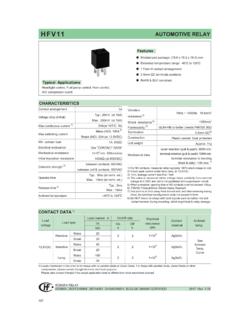
3 C. Not suitable for double relay adding load ) See "Load limit curve" for ) 1min, leakage current less than ) The value is measured when voltage drops suddenly from nominal voltage to 0 VDC and coil is not paralleled with suppression ) When non-energized,close time of NO contacts shall not exceed 10 s, When energized, opening time of closed NO contacts shall not exceed 10 ) Since it is an environmental friendly product, please select lead-free solder when welding. The recommended soldering temperature and time is (2603) , ( ) )Initial value,Equivalent to the max. initial contact resistance is 100m (at 1A 6 VDC).HFKA/HFKA-T25A motor locked loadExtremely small relayChange-over contact versionSingle and twin version availableCoil wire insulation class H (180) HFKA-T (reflow soldering version) availableRoHS & ELV compliantAUTOMOTIVE RELAY CONTACT DATA 3)CHARACTERISTICSat 23 Central door lock, Power doors and windows,Indicator lamp control, Seat adjustment, Sunroof motor control,Mirror adjustment, Wiper weightNONCV ibration resistance 6)Shock resistance 6)TerminationVoltage drop (initial) 1)Ambient temperature1212 ) Corresponds to the peak inrush current on initial actuation (motor).
4 2) When applied in flasher, a special silver alloy (AgSnO2) contact material should be used and the customer special code should be (170) as asuffix. Please heed the anode and cathode's request when wired, common terminal should connect with ) When the load requirement is different from content of the table above, please contact Hongfa for relay application ) Max. allowable overdrive voltage is stated with no load Dimensions30 HFKA: StandardHFKA-T: Reflow soldering version/(XXX)x(110%)2Z: 2 Form C (Twin version)1Z: 1 Form C (Single version) versionHFKA /012-1 ZTSPCOIL DATACoil resistanceNominalvoltageVDCPick-up voltageVDCDrop-out voltageVDCP ower consumptionWORDERING INFORMATIONType1H: 1 Form A (Single version)2H: 2 Form A (Twin version)1Z: 1 Form C (Single version)2Z: 2 Form C (Twin version)Coil voltage 012: 12 VDCC ontact material T: AgSnO2 Coil power P: Low pick-up voltage Nil: StandardConstruction S: Plastic sealed 1) Nil.
5 Flux proofed23 OUTLINE DIMENSIONS, WIRING DIAGRAM AND PC BOARD LAYOUTC ontact arrangementHFKA (Standard)CPacking style C: Tape and reel packing Nil: Tube packing851251258523238512523 StandardLow pick-up voltageUnit: mmNotes: 1) Contact is recommended for suitable condition and specifications if water cleaning or surface process is involved in assembling relays on code2)XXX: Customer special requirement Nil: Standard2) The customer special requirement express as special code after evaluating by Hongfa. (170) stands for flasher ( )x( )+ + ( )x( )+ + ( )x( )+ + ( )x( )+ + DimensionsRemark: * The additional tin top is max.
6 : 1 Form A (Single version)2H: 2 Form A (Twin version)2x( )x( )4x( )x( )4x( )x( )4x( )x( )6x( )x( )2x( )x( )2x( )x( )4x( )x( )4x( )x( )Remark: * The additional tin top is max. : 1 Form C (Single version)2Z: 2 Form C (Twin version)1H: 1 Form A (Single version)2H: 2 Form A (Twin version)2x( )x( )OUTLINE DIMENSIONS, WIRING DIAGRAM AND PC BOARD LAYOUTHFKA-T (Reflow soldering version / High-temperature version)Unit: + + + + + + ( )x( )+ + ( )x( )+ + + + + + + + + + + + + + + + Layout(Bottom view)Wiring Diagram(Bottom view)+ + + + + + + + : 1 Form C (Single version)2Z: 2 Form C (Twin version)1H: 1 Form A (Single version)2H: 2 Form A (Twin version)1Z: 1 Form C (Single version)2Z: 2 Form C (Twin version)1H: 1 Form A (Single version)2H.
7 2 Form A (Twin version)OUTLINE DIMENSIONS, WIRING DIAGRAM AND PC BOARD LAYOUTUnit: mm4 14 ( )6 ( )4 133 Unit: mmTAPE AND REEL PACKINGReelCover tapeEmbossedcarrier tapeI4:1 IDirection of Relay InsertionReel Dimensions2 13-R1adhesive tapeCover tapeadhesive tapeFeed directionduring customer usageat least 3 emptyrelay positionsat least 2 emptyrelay positionsCover tape34 Remark: * For Single relay, L is 20mm; for Twin relay, L is Coil operating voltage rangeAmbient temperature ()1) There should be no contact load applied when maximumcontinuous operation voltage is applied on ) The operating voltage is connected with coil pre-energized time and voltage.
8 After pre-energized, theoperating voltage will ) The maximum allowable coil temperature is 180. Forthe coil temperature rise which is measured byresistance is average value, we recommend the coiltemperature should be below 170 under the differentapplication ambient, different coil voltage and differentload ) If the actual operating coil voltage is out of the specifiedrange, please contact Hongfa for further temperature ()1) There should be no contact load applied when maximumcontinuous operation voltage is applied on ) The operating voltage is connected with coil pre-energized time and voltage. After pre-energized, theoperating voltage will ) The maximum allowable coil temperature is 180.
9 Forthe coil temperature rise which is measured byresistance is average value, we recommend the coiltemperature should be below 170 under the differentapplication ambient, different coil voltage and differentload ) If the actual operating coil voltage is out of the specifiedrange, please contact Hongfa for further : mmTAPE AND REEL PACKINGCHARACTERISTIC CURVES225 coil resistanceUpick-up (after pre-energization under Unomi.) (initial)180 coil resistanceUpick-up (after pre-energization under Unomi.) (initial)Tape Dimensions42L *051020253501214161846810301) This chart takes NO contact, resistive load as ) The load and electrical endurance tests are madeaccording to CONTACT DATA parameters actual load voltage, current or operate frequencyis different from CONTACT DATA table, pleasearrange corresponding tests for Load limit curve (at 23)Switching current (A)3.
10 Reflow soldering, temperature on PCB board.(Recommended soldering temperature, only for reflow soldering version)35 CHARACTERISTIC CURVES2() (s)SolderingPreheatingDisclaimerThe specification is for reference only. See to "Terminology and Guidelines" for more information. Specifications subject to change without case there is specific criterion (such as mission profile, technical specification, PPAP etc.) checked and agreed by and between customer and Hongfa,this specific criterion should be taken as standard regarding any requirement on Hongfa could not evaluate all the performance and all the parameters for every possible application. Thus the user should be in a right position to choosethe suitable product for their own application.