Transcription of HIGH EFFICIENCY 16 SEER AIR CONDITIONER 410A …
1 FR. IG. N. ERA T. NXA6. RE. LY SOUND. Performance Series TAL. EN. Product Specifications M. N. ENVIRO. high EFFICIENCY 16 seer AIR CONDITIONER . ENVIRONMENTALLY SOUND R 410A REFRIGERANT. 1 THRU 5 TONS split system . 208 / 230 Volt, 1 phase, 60 Hz REFRIGERATION CIRCUIT. S Copelandr compressors on all models S Filter Drier supplied with every unit for field installation S Copper tube / aluminum fin coil S ^48 and ^60 models for higher seer , lower capacity S ^49 and ^61 models for higher capacity, lower seer . EASY TO INSTALL AND SERVICE. S Easy Access service valves on all models S External high and low refrigerant service ports S Only two screws to access control panel S Factory charged with R 410A refrigerant BUILT TO LAST. S Baked on powder coat finish over galvanized steel S Post painted (black) coil fins S Coated, weather resistant cabinet screws This product has been designed and manufactured to S Coated inlet grille with 3/8 (10mm) spacing for extra meet ENERGY STAR criteria for energy EFFICIENCY when matched with appropriate coil components.
2 However, protection proper refrigerant charge and proper air flow are critical to achieve rated capacity and EFFICIENCY . Installation of WARRANTY* this product should follow the manufacturer's refrigerant charging and air flow instructions. Failure to confirm S 5 year compressor limited warranty proper charge and airflow may reduce energy EFFICIENCY and shorten equipment life. S 5 year parts limited warranty (including compressor and coil). With timely registration, an additional 5 year parts limited warranty (including compressor and coil). * Applies to original purchaser/homeowner, some limitations may apply. See Warranty certificate for Use of the AHRI Certified TM Mark indicates a complete details. manufacturer's participation in the program. For verification of certification for individual products, go to.
3 Model Size Nominal Min. Circuit Max. Fuse Operating Dimensions Ship / Operating Number (tons) BTU/hr Ampacity or Breaker height x width x depth in. (mm) Weight lbs. (kg). 28 11/16 x 25 3/4 x 25 3/4 154 / 125. NXA618 GKA 1 18,000 20. (729 x 654 x 654) (70 / 57). 28 5/16 x 31 3/16 x 31 3/16 147 / 183. NXA624 GKA 2 24,000 25. (719 x 792 x 792) (83 / 67). 32 5/16 x 31 3/16 x 31 3/16 188 / 153. NXA630 GKA 2 30,000 25. (821 x 792 x 792) (85 / 69). 28 5/16 x 35 x 35 204 / 165. NXA636 GKA 3 36,000 30. (719 x 889 x 889) (93 / 75). 39 1/8 x 35 x 35 254 / 213. NXA642 GKA 3 42,000 40. (994 x 889 x 889) (115 / 96). 39 1/8 x 35 x 35 317 / 264. NXA648 GKA 4 48,000 40. (994 x 889 x 889) (144 / 120). 39 1/8 x 35 x 35 269 / 231. NXA649 GKA 4 48,000 40. (994 x 889 x 889) (122 / 105).
4 45 15/16 x 35 x 35 310 / 272. NXA660 GKA 5 60,000 40. (1167 x 889 x 889) (141 / 123). 45 15/16 x 35 x 35 310 / 272. NXA661 GKA 5 60,000 50. (1167 x 889 x 889) (141 / 123). Specifications subject to change without notice. 421 41 6200 00 July 2010. PRODUCT SPECIFICATIONS split system Air CONDITIONER : NXA6. OUTDOOR UNIT MODEL NUMBER IDENTIFICATION GUIDE (single phase). Digit Position: 1 2 3 4 5, 6 7 8 9 10 11 12. Example Part Number: N X A 6 18 G K A 1 0 0. C = Comfortmaker Mainline N = Comfortmaker Entry BRANDING. X = R 410A REFRIGERANT. A = Air CONDITIONER H = Heat Pump TYPE. 4 = 14 seer . 6 = 16 seer NOMINAL EFFICIENCY . 18 = 18,000 BTUH = 1 tons 24 = 24,000 BTUH = 2 tons 30 = 30,000 BTUH = 2 tons 36 = 36,000 BTUH = 3 tons 42 = 42,000 BTUH = 3 tons 48 = 48,000 BTUH = 4 tons 49 = 48,000 BTUH = 4 tons 60 = 60,000 BTUH = 5 tons 61 = 60,000 BTUH = 5 tons NOMINAL CAPACITY.
5 A = Standard Grille G = Coil Guard Grille C = Coastal FEATURES. K = 208/230 1 60 VOLTAGE. Sales Code Engineering Revision Extra Digit Extra Digit ACCESSORIES PART NUMBER IDENTIFICATION GUIDE. Digit Position: 1 2 3 4 5 6, 7 8, 9 10, 11. Example Part Number: N A S A 0 01 01 CH. N = Non Branded BRANDING. A = Accessory PRODUCT GROUP. S = split system (AC & HP) KIT USAGE. A = Original B = 2nd Generation MAJOR SERIES. 0 = Generic or Not Applicable 2 = R 22. 4 = R 410A REFRIGERANT. Product Identifier Number Package Quantity Type of Kit (Example: CH = Crankcase Heater). International Comfort Products, LLC. Lewisburg, Tennessee 37091 USA. 2 Specifications subject to change without notice. 421 41 6200 00. 421 41 6200 00. PRODUCT SPECIFICATIONS. 4. CENTER OF GRAVITY.
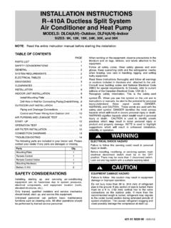
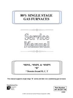
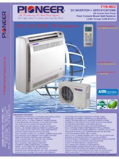
6 A SQ. M. AIR IN AIR. AIR DISCHARGE DISCHARGE. G. FIELD CONTROL AIR IN. SUPPLY CONN. 7/8I HOLE. B. FIELD POWER SUPPLY CONN. F. 7/8I HOLE WITH. Specifications subject to change without notice. 1 1/8I KNOCKOUT AIR IN. 3/8I N. LIQUID LINE CONN. P. C 3 1/2I 3I. E. 1 7/8I. D VAPOR LINE CONN. L. 3/8I TIEDOWN KNOCKOUTS. 5/16I (2) PLACES. AIR IN. K. All Dimensions Inches (English). split system Air CONDITIONER : NXA6. Model Minimum Crated Dimensions A B C D E F G K L M N P. Mounting Pad Size HxWxD. NXA618 GKA 25 3/4 28 11/16 3 3/4 3/4 4 7/16 21 1/4 7 13/16 2 13/16 1/2 13 5/8 13 1/2 12 3/4 26 x 26 32 9/16x30 1/16x26 7/8. NXA624 GKA 31 3/16 28 5/16 3 3/4 3/4 6 9/16 24 11/16 9 1/8 2 13/16 1/2 16 16 13 31 1/2 x 31 1/2 32 9/16x35 1/2x32 3/8. NXA630 GKA 31 3/16 32 5/16 3 3/4 3/4 6 9/16 24 11/16 9 1/8 2 13/16 1/2 15 1/2 16 14 1/4 31 1/2 x 31 1/2 35 15/16x35 1/2x32 3/8.
7 NXA636 GKA 35 28 5/16 3 7/8 7/8 6 9/16 28 7/16 9 1/8 2 15/16 5/8 16 16 13 35 x 35 32 9/16x39 5/16x36 1/8. NXA642 GKA 35 39 1/8 3 7/8 7/8 6 9/16 28 7/16 9 1/8 2 15/16 5/8 16 1/2 17 1/2 17 1/2 35 x 35 42 3/4x39 5/16x36 1/8. NXA648 GKA 35 39 1/8 3 7/8 7/8 6 9/16 28 7/16 9 1/8 2 15/16 5/8 17 1/2 16 1/2 15 35 x 35 42 3/4x39 5/16x36 1/8. NXA649 GKA 35 39 1/8 3 7/8 7/8 6 9/16 28 7/16 9 1/8 2 15/16 5/8 17 1/2 16 1/2 15 35 x 35 42 3/4x39 5/16x36 1/8. NXA660 GKA 35 45 15/16 3 7/8 7/8 6 9/16 28 7/16 9 1/8 2 15/16 5/8 16 1/2 17 16 1/4 35 x 35 49 9/16x39 5/16x36 1/8. NXA661 GKA 35 45 15/16 3 7/8 7/8 6 9/16 28 7/16 9 1/8 2 15/16 5/8 16 1/2 17 16 1/4 35 x 35 49 9/16x39 5/16x36 1/8. 3. 4. PRODUCT SPECIFICATIONS. A SQ. M. AIR. AIR IN. AIR DISCHARGE DISCHARGE. G. FIELD CONTROL AIR IN.
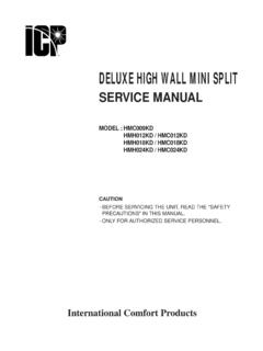
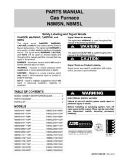
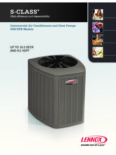
8 SUPPLY CONN. HOLE. B. FIELD POWER SUPPLY CONN. F. HOLE WITH. KNOCKOUT AIR IN. Specifications subject to change without notice. N. LIQUID LINE CONN. P. C E. D VAPOR LINE CONN. L. TIEDOWN KNOCKOUTS. (2) PLACES. AIR IN. K. Dimensions mm (SI Metric). Model Minimum Crated Dimensions split system Air CONDITIONER : NXA6. A B C D E F G K L M N P. Mounting Pad Size HxWxD. NXA618 GKA 654 729 95 19 113 540 198 71 13 346 343 324 660 x 660 827 x 764 x 683. NXA624 GKA 792 719 95 19 167 627 232 71 13 406 406 330 800 x 800 827 x 902 x 822. NXA630 GKA 792 821 95 19 167 627 232 71 13 394 406 362 800 x 800 913 x 902 x 822. NXA636 GKA 889 719 98 22 167 722 232 75 16 406 406 330 889 x 889 827 x 999 x 918. NXA642 GKA 889 994 98 22 167 722 232 75 16 419 445 445 889 x 889 1086 x 999 x 918.
9 NXA648 GKA 889 994 98 22 167 722 232 75 16 445 419 381 889 x 889 1086 x 999 x 918. 421 41 6200 00. NXA649 GKA 889 994 98 22 167 722 232 75 16 445 419 381 889 x 889 1086 x 999 x 918. NXA660 GKA 889 1167 98 22 167 722 232 75 16 419 431 413 889 x 889 1259 x 999 x 918. NXA661 GKA 889 1167 98 22 167 722 232 75 16 419 431 413 889 x 889 1259 x 999 x 918. PRODUCT SPECIFICATIONS split system Air CONDITIONER : NXA6. PHYSICAL DATA. Model Size 18 24 30 36 42 48 49 60 61. Nominal Cooling Capacity (BTU/hr) 18,000 24,000 30,000 36,000 42,000 48,000 48,000 60,000 60,000. Nominal seer Sound Rating (dBA)** 76 76 76 76 78 78 78 78 79. PSC Fan Motor HP 1/12 1/10 1/10 1/12 1/5 1/4 1/4 1/4 1/4. Fan RPM (single speed) 1100 1100 1100 830 830 830 830 830 830. Fan CFM 1900 2600 2600 3200 3800 4100 4100 4100 4100.
10 Coil Face Area ft2 (m2). ( ) ( ) ( ) ( ) ( ) ( ) ( ) ( ) ( ). Coil Rows fins per inch 1 25 1 25 1 25 1 25 1 25 2 20 1 25 2 20 2 20. Liquid Line Connection Size in. (mm) 3/8 (10) 3/8 (10) 3/8 (10) 3/8 (10) 3/8 (10) 3/8 (10) 3/8 (10) 3/8 (10) 3/8 (10). Vapor Line Connection Size in. (mm) 3/4 (19) 3/4 (19) 3/4 (19) 7/8 (22) 7/8 (22) 7/8 (22) 7/8 (22) 7/8 (22) 7/8 (22). Recommended Line Set Liquid Tube 3/8 3/8 3/8 3/8 3/8 3/8 3/8 3/8 3/8. Diameter in. (mm) (10) (10) (10) (10) (10) (10) (10) (10) (10). Recommended Line Set Vapor Tube 3/4 3/4 3/4 7/8 7/8 7/8 7/8 1 1/8 1 1/8. Diameter in. (mm) (19) * (19) * (19) * (22)* (22)* (22)* (22)* (29)* (29)*. * Recommended Vapor Tube Line size is for standard installations. These recommendations may not apply to Long Line installations.