Transcription of High-Efficiency Feedhorns for Prime-focus Dishes
1 High-Efficiency Feedhorns for Prime-focus Dishes VE4MA and Chaparral feeds with Septum Polarizers Paul Wade W1 GHZ 2006 measurements by Tommy Henderson WD5 AGO This started out to be a simple project optimize the VE4MA feedhorn1 with a septum polarizer2 for circular polarization. Some unexpected results have led to a larger analysis with conclusions that may differ from the prevailing wisdom, but have been verified by measurements made by WD5 AGO. Some improved variations of the VE4MA and Chaparral Feedhorns are described which show some of the highest calculated and measured efficiencies to date for a Prime-focus dish.
2 What we often call a feedhorn includes several separate elements: an antenna which shapes the beam for improved dish illumination, a waveguide section (round, square, or rectangular), perhaps a circular polarizer, and an excitation region (waveguide, probe transition to coax, or other transition). While these elements may interact, each has a separate function and may be analyzed independently. It is not necessary to exactly replicate all the dimensions from end-to-end, but it would be foolhardy to make changes without considering possible interactions. Thus, we will separate the following elements for examination: VE4MA horn Chaparral-style horn Septum polarizer in circular waveguide VE4MA and Chaparral horns with septum polarizer The excitation is a separate problem; all analysis here, using Ansoft HFSS software3, will use single-mode waveguide excitation.
3 Probe transitions in circular waveguide were studied in a previous paper4, so probes will not be included here. The probe is not part of the antenna. The only complication which might be added by probe excitation would be additional waveguide modes; if the waveguide section preceding the horn is sufficiently long, then the additional modes will not reach the horn and thus not affect the radiation pattern. Single-mode excitation eliminates this potential complication from the analysis. Dish illumination review The ideal illumination for a parabolic dish antenna would provide uniform energy over the reflector surface, with no spillover energy missing the dish.
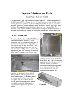
4 Real feed antennas do not provide this ideal distribution. Figure 1, from the W1 GHZ Microwave Antenna Book Online5, shows the desired illumination vs. a typical (idealized) feed pattern. The typical pattern energy decreases from the central peak, while the desired pattern energy increases toward the edges to compensate for space attenuation the edge of the dish is farther from the feed than the center of the dish. f/D = Illumination taper = 10 dBFigure 1. Typical vs. Desired Dish IlluminationN1 BWT 19940 dB-10 dB-20 dBSpillover lossIllumination lossThe typical feed pattern also has spillover energy which misses the reflector, and real feeds have sidelobes and backlobes which also waste energy.
5 For many feeds, it has been found that the tradeoff between illumination and spillover yielding best efficiency occurs when the illumination (not the feed pattern we must account for space attenuation) is about 10 dB down at the edge of the dish. This 10 dB feed taper is just a rule-of-thumb; for accurate analysis, we use pattern integration, calculating the efficiency for the full three-dimensional feed pattern (in practice, for well behaved feeds, only a few cuts, typically the E- and H-plane cuts, through the 3D pattern are necessary). Note: all efficiency calculations are for an arbitrary 20 dish diameter and a feed diameter, or a constant blockage ratio of , so that we are comparing apples to apples.
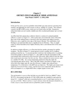
6 For small Dishes , the actual blockage is more significant and efficiency should be recalculated. VE4MA Feed The VE4MA feed1 is based on a paper by Kumar6. This horn, which adds a single ring around a circular waveguide (Figure 2), has patterns shown in both papers which are not maximum at the center, but rather increase somewhat like our desired feed before tapering off like a typical feed see Figure 1. Thus, the pattern, shown in Figure 3, tends to be more like the desired illumination, and provides somewhat better efficiency than a simple feed, for instance, the open circular waveguide ( coffee-can feed ) without the ring.
7 The pattern and efficiency plots for open circular waveguide feeds are shown in Figure 4; calculated efficiency is lower than the VE4MA feed for all but the largest diameters, and those larger diameters are large enough to propagate additional modes which will degrade the performance. It was suggested by Kumar that a ring dimension, wide x deep, forms a resonant structure which creates the improved pattern. Therefore, hams have carefully duplicated the dimensions published by Barry, VE4MA, for this feed, with very good results. One reason for the popularity of this feed is that it works well for conventional Dishes over a wide range of f/D; the feed is optimized by the position of the ring with respect to the rim of the central horn.
8 Original VE4MA Feed horn diameterRing wide x deep, behind rimFigure 3 Dish diameter = 20 Feed diameter = E-plane H-plane 0 dB-10 -20 -30 Feed Radiation PatternW1 GHZ Angle aroundFeed Phase AngleE-planeH-planespecifiedPhase Center = beyond dB2 dB3 dB4 dB5 dB6 dB7 dB8 dBMAX Possible efficiency with Phase errorREAL WORLD at least 15% lowerMAX efficiency without phase errorIllumination Spillover AFTER LOSSES:Feed Blockage Parabolic Dish f/DParabolic Dish efficiency %Cylindrical waveguide feeds, no ring"Coffee-can Feed"Figure 4 Dish diameter = 20 Feed diameters listedE-plane H-plane 0 dB-10 -20 -30 Feed Radiation PatternW1 GHZ Angle aroundFeed Phase AngleE-planeH-planespecifiedPhase Center = 0 beyond dB2 dB3 dB4 dB5 dB6 dB7 dB8 dBMAX Possible efficiency with Phase errorREAL WORLD at least 15% diameterParabolic Dish f/DParabolic Dish efficiency % If the ring is resonant, there should be a clear peak in performance with dimensions which are resonant.
9 However, when I first varied the dimensions, the only slight peak was with one ring position, with the ring behind the rim of the central horn. Varying the other dimensions, I could find no peak at all either there is no peak, or it is so sharp that we have no hope of duplicating it. The performance was nearly identical over a broad range of dimensions, suggesting that we could make better use of available materials. Performance was slightly better over a range of smaller ring dimensions, which would have the additional benefit of reduced blockage. The improvement with a smaller ring could be significant for the smaller Dishes used by many hams.
10 VE4MA feed - x lambda position - wavelengths behind rimDish efficiency (%) f/DHorn Diameter Figure 5. VE4MA feed horn diameter comparison The VE4MA dimensions specify a circular waveguide horn diameter of . My previous work with the OK1 DFC septum found that the septum worked best with a diameter circular waveguide, so most of the variations in ring dimensions I tried were with the smaller diameter so that they would also work with a septum polarizer. However, comparing Feedhorns with the same ring dimensions on the two different diameter horns showed little difference, as illustrated in Figure 5 for the original ring dimensions of wide and deep, and for a smaller ring of wide and deep in Figure 6 below.