Transcription of High Mast Lighting Systems - Foundation Design
1 High mast systemsTypes of subsoilCondition of subsoilField test applicableApproximate allowance bearing pressure kN/m2 RockNot inferior to sandstone, limestone or firm chalkRequires at least a pneumatic or other mechanically operated pick for excavation1000 Gravel, sandCompactRequires pick for excavation. Wooden peg 50mm2 in cross section is hard to drive beyond 150mmDense to very dense 150-400 Loose to medium dense 50-250 Clay, sandy clayFirmCan be moulded by substantial pressure with the fingers and excavated with graft or spade50-100 Sand*, silty sand*, clayey sand*LooseCan be excavated with a spade. Wooden peg 50mm2 in cross section can be easily driven<75 Silt*, clay*, sandy clay*, silty clay*SoftFairly easily moulded with the fingers and readily excavated<75 Silt*, clay*, sandy clay*, silty clay*Very softNatural sample in winter conditions exudes between fingers when squeezed in fist<75 These values are provided for guidance only.
2 If in any doubt, consult a qualified civil engineer.*Foundations on these soils require assessment and Design by a qualified civil of subsoil Foundation designIn this section, you ll find technical guidance on Foundation designs for both the range of high masts in this brochure and bespoke masts designed by Abacus for specific clients projects. All foundations meet BS8004 standards and comply with the Institute of Lighting Engineers Technical Report key factor in determining the size of mast foundations is the bearing pressure of the ground in which it will the following pages, each standard Foundation reference incorporates the ground-bearing pressure within its code, making it quick and simple to identify the kind of Foundation you table below shows subsoil classifications according to the BS8004 standard, against the approximate allowable bearing pressure.
3 We're also working to the new eurocodes, so if you require any further help, please call us on +44 (0)1623 511 there is any doubt over ground conditions, it is the client s or contractor s responsibility to consult a qualified civil engineer to establish the true bearing Foundation details are provided for guidance only and should be checked with the client before use. Abacus Lighting Limited will not accept responsibility for any foundations unless they are specifically designed by us at the client s ground-bearing mast Systems 51 Cables buried directly in the ground must be marked by cable covers or a suitable marking , conduits and ducts must be buried deep enough to avoid damage from any reasonably foreseeable ground disturbance.
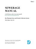
4 If you are in any doubt, refer to national guidelines or the site: cable trenchesSquare bolt configuration, with bolt centre dimensionsCircular bolt configuration, with PCD bolt centre dimensions600mm minbolt centre dimensiontopsoilselected fillsand150 min450mm to top of cable min150mm min /300mm maxThe principal method for installing a high mast involves a flange plate supported by a prepared Foundation *.The flange plate, which is welded to the base of the mast, is designed to accommodate the overturning moments (forces) for each specific holes in the flange plate are arranged in one of two ways:1. In a square, where the stated bolt centre dimension is In a circle, where the pitch circle diameter (PCD), is given.
5 This diameter is stated for the dimension between bolt-hole centres (see diagram).* Root-mounting can be an option up to a height of 18m, but we don t cover this here. If you d like more information on this method, please contact the Abacus sales and flange platesTypical cable High mast systemsFoundation bolts Foundation bolts are supplied with nuts, washers, a spacer plate and a fixing template in either wood (smaller masts) or steel. Make sure the Foundation bolt is put together accurately with bolts vertical and fixed rigidly so it won t be displaced or misaligned during concreting. Also, check that bolts project correctly above the the concrete has cured, the mast is erected and levelled on the double bolts should then be tightened in accordance with the final torque value, as shown in the table to the should be constructed in accordance with the following Design and dimensional details.
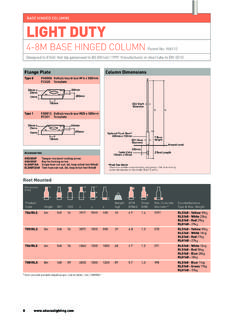
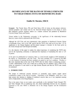
6 Unless otherwise specified, they should use: For reinforced foundations: grade C28/35 concrete and high tensile reinforcement with a yield stress of 485N/mm For unreinforced foundations: C20/25 grade entry ducts should be placed centrally within the concrete to facilitate entry into (and in some cases out of) the mast will typically take a minimum of 14 days to cure enough to erect the mast subject to various factors and in accordance with recommendations. Assembling Foundation bolts into concreteThe Foundation reference codes on the following pages are put together like this:Glossary of Foundation reference codesBolt size and gradeProjection (mm)Torque (Nm)
7 M16*500 long grade *500 long grade *600 long grade *800 long grade *880 long grade *1220 long grade *1200 long grade *1350 long grade *1590 long grade *1700 long grade *1870 long grade bolt projection and final torque valuesTypical section through foundationTemplateBolt projectionTemporary supportCable ductSpacer plateBAType of foundationPPassive mass concreteMNon-passive mass concreteRReinforced 500M150 Overturning moment kNmGround bearing pressure mast Systems 53We offer two standard concrete types for non- reinforced -mass Foundation designs passive and concrete : passive and non-passive (kNm)Bearing pressure (kN/m )A Width (mm)B depth (mm)3P15031506507504P15041507008005P1505 1507508006P15061507509008P15081508509501 0P1501015090095015P15015150950110020P150 201501050120030P150301501200125040P15040 1501250130050P150501501350140075P1507515 014501600100P15010015016001700150P150150 15018001850200P15020015019502000300P1503 0015022502150400P15040015024502250500P15 050015027002300750P15075015030502600 Ground bearing pressures below 150 kN/m2 are not concrete Foundation Standard (kNm)Bearing pressure (kN/m )A Width (mm)B depth (mm)
8 3M753758805903M10031008805903M1503150880 5904M754759506254M10041009506254M1504150 9506255M7557510506755M100510010506755M15 0515010506756M7567511007006M100610011007 006M150615011007008M7587511507258M100810 011507258M1508150115072510M7510751250775 10M10010100125077510M15010150125077515M7 51575140085015M10015100135082515M1501515 0135082520M752075150090020M1002010015009 0020M15020150150090030M7530751700100030M 100301001700100030M150301501700100040M75 40751900110040M100401001800105040M150401 501800105050M7550752100120050M1005010019 00110050M150501501900110075M757575240013 5075M100751002200125075M1507515022001250 100M751007526501475100M10010010024001350 100M15010015023001300150M751507532001750 150M10015010027001650150M150150150250014 00200M752007539002100200M100200100300016 50200M15020015027001500300M1003001003500 1900300M15030015031001700400M10040010021 003900400M15040015034001850500M100500100 45002400500M15050015036001950750M1507501 5041002200 Non-passive concrete Foundation Standard sizesPassive concreteTypically used in firm ground with ground-bearing pressure of no less than 150kN/m Non-passive concreteTypically used with uniform or poor subsoil with ground-bearing pressure of 75-150kN/m Soil pressure distributionSoil pressure High mast systemsStandard reinforced foundationsFoundation (kNm)Bearing pressure (kN/m2)A (mm)B (mm)C (mm)D (mm)Base reinforcement (Each way 21)Column reinforcement (All round 11)To p reinforcement (Each way 21)75R75757511009506002400H16@250 t and bH20@22575R1507515011009506002050H16@250 t and bH20@225100R751007511009506002600H16@250 t and bH20@225100R15010015011009506002300H16@2 50 t and bH20@225150R7515075110013506002900H16@25 0 t and bH20@225150R150150150110013506002500H16@ 250 t and bH20@225200R7520075110013506003200H16@25 0 t and bH20@225200R150200150110013506002750H16@ 250 t and bH20@225300R7530075150013507503700H16@20 0 t and bH20@150300R150300150150013507503100H16@ 200 t and bH20@150400R7540075150015007504100H16@20 0 t and bH20@150H16@175400R150400150150015007503 400H16@200 t and bH20@150500R7550075150015007504400H16@20 0 t and bH20@150500R150500150150015007503700H16@ 200 t and bH20@150750R7575075150015007505000H16@20 0 t and bH20@125750R150750150150015007504200H16@ 200 t and bH20@1251000R75100075150018507505500H20@ 250 t and bH25@1501000R1501000150150018507504700H2 0@250 t and bH25@1501250R75125075150018507505900H20@ 200 t and bH25@1251250R1501250150150018507505000H2 0@200 t and bH25@1251500R751500751500185010006800H20 @150 t and bH32@1751500R15015001501500185010005400H 16@150 t and bH32@1752000R752000752000200010007000H20 @250t and bH25@1502000R10020001002000200010006000H 20@250t and bH25@1502000R15020001502000200010005500H 20@250t and bH25@1503000R753000752100200012507750H20 @200t and bH25@1503000R10030001002100200012507000H 20@200t and bH25@1503000R15030001502100200012506250H 20@200t and bH25@1504000R754000752100200015008500H20 @175t and bH32@1504000R10040001002100200015007750H 20@175t and bH32@1504000R15040001502100200015007000H 20@175t and bH32@1505000R755000752100200015009000H20 @175t and bH32@1505000R10050001002100200015008250H 20@175t and bH32@1505000R15050001502100200015007500H 20@175t and bH32@150H16@1756000R75600075250020001500 9500H20@250t and bH32@1506000R10060001002500200015008750H 20@250t and bH32@1506000R15060001502500200015008000H 20@250t and bH32@1507000R7570007525002000150010000H2 5@225t and bH32@1507000R10070001002500200015009250H 25@225t and bH32@1507000R15070001502500200015008250H 25@225t and bH32@1508000R7580007526002000150010500H3 2@200b + H25@250tH32@1508000R10080001002600200015 009600H25@225t and bH32@1508000R15080001502600200015008700H 25@225t and bH32@1509000R7590007526002000150011000H3 2@175b H25@225tH32@1259000R10090001002600200015 0010000H25@200t and bH32@1259000R15090001502600200015009000H 25@225t and concrete to have a minimum characteristic strength of 35 N/mm2 at 28 days.
9 Minimum cement content t