Transcription of High noise immunity 74HC4053; 74HCT4053 - Nexperia
1 74HC4053; 74 HCT4053. Triple 2-channel analog multiplexer / demultiplexer Rev. 11 9 September 2021 Product data sheet 1. General description The 74HC4053; 74 HCT4053 is a triple single-pole double-throw analog switch (3x SPDT) suitable for use in analog or digital 2:1 multiplexer / demultiplexer applications. Each switch features a digital select input (Sn), two independent inputs/outputs (nY0 and nY1) and a common input/output (nZ). A digital enable input (E) is common to all switches. When E is HIGH, the switches are turned off. Inputs include clamp diodes. This enables the use of current limiting resistors to interface inputs to voltages in excess of VCC. 2. Features and benefits Wide analog input voltage range from -5 V to +5 V.
2 CMOS low power dissipation High noise immunity Latch-up performance exceeds 100 mA per JESD78 Class II Level B. Complies with JEDEC standard: JESD8C ( V to V). JESD7A ( V to V). Low ON resistance: 80 (typical) at VCC - VEE = V. 70 (typical) at VCC - VEE = V. 60 (typical) at VCC - VEE = V. Logic level translation: to enable 5 V logic to communicate with 5 V analog signals Typical break before make' built-in ESD protection: HBM JESD22-A114F exceeds 2000 V. MM JESD22-A115-A exceeds 200 V. CDM JESD22-C101E exceeds 1000 V. Multiple package options Specified from -40 C to +85 C and -40 C to +125 C. 3. Applications analog multiplexing and demultiplexing Digital multiplexing and demultiplexing Signal gating Nexperia 74HC4053; 74 HCT4053.
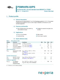
3 Triple 2-channel analog multiplexer / demultiplexer 4. Ordering information Table 1. Ordering information Type number Package Temperature range Name Description Version 74HC4053D -40 C to +125 C SO16 plastic small outline package; 16 leads; SOT109-1. 74 HCT4053D body width mm 74HC4053PW -40 C to +125 C TSSOP16 plastic thin shrink small outline package; 16 leads; SOT403-1. 74 HCT4053PW body width mm 74HC4053BQ -40 C to +125 C DHVQFN16 plastic dual in-line compatible thermal enhanced SOT763-1. 74 HCT4053BQ very thin quad flat package; no leads; 16 terminals;. body mm 5. Functional diagram E VCC. 6 16. 13 1Y1. S1 11 LOGIC. LEVEL DECODER 12 1Y0. CONVERSION. 14 1Z. 1 2Y1. S2 10 LOGIC.
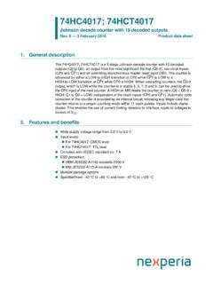
4 LEVEL 2 2Y0. CONVERSION. 15 2Z. 3 3Y1. S3 9 LOGIC. LEVEL 5 3Y0. CONVERSION. 4 3Z. 8 7. GND VEE 001aak341. Fig. 1. Functional diagram 74HC_HCT4053 All information provided in this document is subject to legal disclaimers. Nexperia 2021. All rights reserved Product data sheet Rev. 11 9 September 2021 2 / 25. Nexperia 74HC4053; 74 HCT4053. Triple 2-channel analog multiplexer / demultiplexer 6. EN. 11 S1 1Y0 12. 10 S2 1Y1 13 MUX/DMUX. 11 # 0 12. 9 S3 1Z 14 0. 1. 14 13. 2Y0 2 0/1 1. 2Y1 1 10 # 2. 2Z 15 15 1. 3Y0 5. 9 # 5. 3Y1 3. 4 3. 6 E 3Z 4. 001aae125 001aae126. Fig. 2. Logic symbol Fig. 3. IEC logic symbol Y. VCC VEE. VCC VCC. VCC VEE. VEE Z. from logic 001aad544. Fig. 4.
5 Schematic diagram (one switch). 74HC_HCT4053 All information provided in this document is subject to legal disclaimers. Nexperia 2021. All rights reserved Product data sheet Rev. 11 9 September 2021 3 / 25. Nexperia 74HC4053; 74 HCT4053. Triple 2-channel analog multiplexer / demultiplexer 6. Pinning information Pinning 74HC4053. 74 HCT4053. 16 VCC. 2Y1. terminal 1. index area 1. 2Y0 2 15 2Z. 3Y1 3 14 1Z. 74HC4053. 74 HCT4053 3Z 4 13 1Y1. 3Y0 5 12 1Y0. 2Y1 1 16 VCC VCC(1). E 6 11 S1. 2Y0 2 15 2Z. VEE 7 10 S2. 3Y1 3 14 1Z. 8. 9. 3Z 4 13 1Y1. S3. GND. 3Y0 5 12 1Y0 001aae128. E 6 11 S1. Transparent top view VEE 7 10 S2. (1) This is not a supply pin. There is no electrical or GND 8 9 S3.
6 Mechanical requirement to solder the pad. In case 001aae127 soldered, the solder land should remain floating or connected to VCC. Fig. 5. Pin configuration SOT109-1 (SO16) and SOT403-1 (TSSOP16) Fig. 6. Pin configuration SOT763-1 (DHVQFN16). Pin description Table 2. Pin description Symbol Pin Description E 6 enable input (active LOW). VEE 7 supply voltage GND 8 ground supply voltage S1, S2, S3 11, 10, 9 select input 1Y0, 2Y0, 3Y0 12, 2, 5 independent input or output 1Y1, 2Y1, 3Y1 13, 1, 3 independent input or output 1Z, 2Z, 3Z 14, 15, 4 common output or input VCC 16 supply voltage 7. Functional description Table 3. Function table H = HIGH voltage level; L = LOW voltage level; X = don't care.
7 Inputs Channel on E Sn L L nY0 to nZ. L H nY1 to nZ. H X switches off 74HC_HCT4053 All information provided in this document is subject to legal disclaimers. Nexperia 2021. All rights reserved Product data sheet Rev. 11 9 September 2021 4 / 25. Nexperia 74HC4053; 74 HCT4053. Triple 2-channel analog multiplexer / demultiplexer 8. Limiting values Table 4. Limiting values In accordance with the Absolute Maximum Rating System (IEC 60134). Voltages are referenced to VSS = 0 V (ground). Symbol Parameter Conditions Min Max Unit VCC supply voltage [1] + V. IIK input clamping current VI < V or VI > VCC + V - 20 mA. ISK switch clamping current VSW < V or VSW > VCC + V - 20 mA. ISW switch current V < VSW < VCC + V - 25 mA.
8 IEE supply current - 20 mA. ICC supply current - 50 mA. IGND ground current - -50 mA. Tstg storage temperature -65 +150 C. Ptot total power dissipation [2] - 500 mW. P power dissipation per switch - 100 mW. [1] To avoid drawing VCC current out of terminal nZ, when switch current flows into terminals nYn, the voltage drop across the bidirectional switch must not exceed V. If the switch current flows into terminal nZ, no VCC current will flow out of terminals nYn, and in this case there is no limit for the voltage drop across the switch, but the voltages at nYn and nZ may not exceed VCC or VEE. [2] For SOT109-1 (SO16) package: Ptot derates linearly with mW/K above 110 C.
9 For SOT403-1 (TSSOP16) package: Ptot derates linearly with mW/K above 91 C. For SOT763-1 (DHVQFN16) package: Ptot derates linearly with mW/K above 106 C. 9. Recommended operating conditions Table 5. Recommended operating conditions Symbol Parameter Conditions 74HC4053 74 HCT4053 Unit Min Typ Max Min Typ Max VCC supply voltage see Fig. 7 and Fig. 8. VCC - GND V. VCC - VEE V. VI input voltage GND - VCC GND - VCC V. VSW switch voltage VEE - VCC VEE - VCC V. Tamb ambient temperature -40 +25 +125 -40 +25 +125 C. t/ V input transition rise and fall VCC = V - - 625 - - - ns/V. rate VCC = V - 139 - 139 ns/V. VCC = V - - 83 - - - ns/V. VCC = V - - 31 - - - ns/V. 74HC_HCT4053 All information provided in this document is subject to legal disclaimers.
10 Nexperia 2021. All rights reserved Product data sheet Rev. 11 9 September 2021 5 / 25. Nexperia 74HC4053; 74 HCT4053. Triple 2-channel analog multiplexer / demultiplexer 001aad545 001aad546. 10 10. VCC - GND VCC - GND. (V) (V). 8 8. 6 operating area 6. operating area 4 4. 2 2. 0 0. 0 2 4 6 8 10 0 2 4 6 8 10. VCC - VEE (V) VCC - VEE (V). Fig. 7. Guaranteed operating area as a function of the Fig. 8. Guaranteed operating area as a function of the supply voltages for 74HC4053 supply voltages for 74 HCT4053. 10. Static characteristics Table 6. RON resistance per switch for 74HC4053 and 74 HCT4053. VI = VIH or VIL; for test circuit see Fig. 9. Vis is the input voltage at a nYn or nZ terminal, whichever is assigned as an input.