Transcription of High Pressure Hydrogen Tank Manufacturing
1 Department of Energy WorkshopHigh Pressure Hydrogen Tank Manufacturing Mark LeavittQuantum Fuel Systems Technologies Worldwide, Inc. August 11, 2011 This presentation does not contain any proprietary, confidential, or otherwise restricted informationHistory of breakthrough in all-composite lightweight, high capacity, low-cost fuel storage technologies. Developed a series of robust, OEM compatible electronic control H2storage system for SunLine Tran-sit Hythane patent for integrated module including in-tank regulator Developed high efficiency H2fuel storage systems for DOE Future Truck programsDeveloped H2storage and metering system for Toyota s FCEV to certify 10,000 psi systems in Japan Designed, developed and validated advanced fuel storage systems for DaimlerChryslerFirst to fill a H2storage cylinder with compressed H2at 5,000 psi at California Fuel Cell Partnership developed for the Hyundai Santa Fe Fuel Cell Vehicle.
2 Achieved a record of H2 tank efficiency, the highest weight efficiency ever demonstrated, in partnership with Lawrence Livermore National Lab and Thiokol. Developed portable Hydrogen refueling devices and supplied for multiple customer applicationsAwarded patent for mobile Hydrogen refueling systems Developed wt% Hydrogen tank and kg regulatorfor NASA/ AeroVironmentDeveloped electrolyzer based H2mobile refueling system for the US Army Developed on-tank automatic valve system for 10,000 psi H2 First to ship 10,000 psi H2storage fuel system with patented in-tank regulator moduleValidated H2injectors and developed advanced Hydrogen metering systems for FC stackFirst to certify 10,000 psi H2 Storage Tank to International Standards.
3 Developed and implemented advanced process controls, based on experience in producing over 1,600 Hydrogen tanks Awarded patent on injectors for dry gaseous fuels Opened state-of-the art SULEV emissions testing 2003 First to demonstrate an all-composite H2 Storage Tank that stores at 10,000 psi Developed 10,000 psi in-tank Pressure regulator module incorporating two regulators and solenoid valveDeveloped FC hybrid electric Aggressor for the US Army, from the ground-up Developed ultra-light Hydrogen systems for high altitude applications Opened world s first 10,000 psi Hydrogen gas test facility and performs extreme testsDeveloped 2ndgeneration in-tank regulation system for Toyota Developed an integrated plug-and-play fuel storage system for GM HyWire FC concept vehicleBegan developing additional H2 ICE hybrid platforms to follow CNG and PHEV Launched R&D targeting next generation storage and metering systems Developed innovative Hydrogen ICE hybrid electric vehicles for SCAQMDGM s Sequel First Hydrogen Fuel Cell vehicle to go 300 miles without refueling 200420052006 2007 2008 2009 2010 Launched in production CNG (21x60)
4 Vessel lightest in class by 35% Quantum and Fisker form: Fisker Automotive (Q-Drive)First in the industry with drop in CNG tank replacement for HD diesel 25 & 26 tanksBegan development and verification of the Saturated Injector2ndGeneration Military Vehicle intro of Q-ForceElectrification of LLV Quantum Quiet DriveTM2 External Regulator 0 First Stage MPamax inlet Pressure 3 MPanominal outlet Pressure EIHP CertifiedMid-Stage Valve 3 MPanominal working Pressure Electronically controlled shut-off valve using PWM Peak and Hold current Pressure gauge port Auxiliary defueling port with integral flow control orificeRegulator Second Stage 3 MPanominal inlet Pressure 500 kPaGnominal outlet Pressure Outlet Pressure gauge portLow
5 Pressure Lock-off Normally closed 230 psig maximum working Pressure Maximum flow 5g/sec @ 10 psiD Coil resistance 12 Ohms @ 25 C Normal operating voltage to VDC Saturated current Operating temperature -40 C to 85 CH2 Fuel Systems3On-Tank Valve MPamax working Pressure Electronically controlled shut-off valveusing PWM Peak and Hold current Auxiliary bypass valve Thermally activated PRD w/ vent port Tank Pressure & Gas Temp sensors Integral check valve on fill line Water Heating channelsInjectors - Hydrogen Dynamic Flow: mg/pulse (4%), air @ 345 ms pulse width @ 100Hz Static Flow: g/s (5%) air @ 345 kPa Maximum Operating Pressure : 345 kPa Tip Leakage: cc/min H2 compatible seal materials 200M CyclesFuel Lines 10,000 psi nominal working Pressure O-ring face seal connections CNC bent to CAD data 316 Stainless Steel (Other materials available) Welded end form or Parflange(Parker) Flex line availableHigh Pressure Fuel Rails 304 Stainless Steel or 6061 Aluminum Brazed construction (SS)Manufactured Fuel System ComponentsInjectors - CNG Dynamic Flow: mg/pulse (4%), air @ 345 ms pulse width @ 100Hz Static Flow: g/s (5%) air @ 345kPa CNG compatible seal materials Tip Leakage: cc/min Certified to ECE R110 in 2003 500M CyclesIntermediate Pressure Regulator Maximum inlet Pressure .
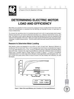
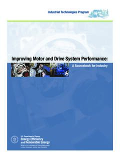
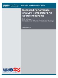
6 MPaG Adjustable outlet Pressure ranges Flow up to m /min, 20 g/s air Operating temperature -40 C to 125 C Aluminum body CNG compatible seal materials4 Tank Manufacturing Barriers Cost Weight Unification of standards Availability of automotive gaseous Hydrogen components5 Tank Cost BreakdownLabor and Overhead9%Material - Fiber63%Material - Metal 19%Material - Other9%Tank Total Manufacturing Cost Cost Breakdown Uses Following Assumptions: 125 liter 10,000 psi H2tank Traditional Manufacturing processes Type IV (plastic liner) tank Annual Production Quantity 10,000 Carbon fiber cost at $15/lb Metal components are 316L stainless steel6 Rotomold OperationLinerPre AnnealInspectionLiner AnnealLinerPost AnnealInspectionLiner Final BoreInspectionFilamentWindingOperationOv en Cure OperationAdapter InstallOperationVolumetricTestLeakTestFu lly Completed Ta n kTank Manufacturing Process7 Quantum Cost Reduction Efforts Advance Manufacturing process combining filament winding with Fiber placement Hybrid tank design using lower cost carbon fiber on exterior layers Alternative fiber evaluation (Basalt)
7 Manufacturing Process Automation8 Filament Winding/Fiber Placement ConceptTo manufacture H2storage Pressure vessels, utilizing a new hybrid process with the following features: Optimize elements of advanced fiber placement (AFP) & commercial filament winding (FW)With the aim of addressing the barriers by achieving a Manufacturing process with:1. lower composite material usage2. higher Manufacturing efficiency9 Background on Hybrid Vessel dome caps (forward and aft) are then removed from foam tooling and brought to wind final stage is to filament wound over the forward and aft dome foam mandrels. Three -inch tows are placed on forward and aft dome caps are then transferred and installed to the Hydrogen storage Accomplishments: Material & Cost SavingImprovements made between Baseline and Vessel 7.
8 Composite mass reduced from 76 kg to kg ( reduction) Specific energy increased from to kWh/kg Cost efficiency reduced from $ to $ for $11/lb carbon fiber Cost efficiency would reduce from $ to $ for $6/lb carbon fiber11 Hybrid tank design using lower cost carbon fibers on exteriorHelical LayersHoop Layers~25% strain decrease from inside to outside layers12 Hybrid tank design using lower cost carbon fibers on exterior By replacing outside layers with lower cost fiber overall fiber cost can be decrease with no or little impact on tank weight Preliminary calculation give a weight increase of and a cost savings of 4% Outer layers also utilize higher modulus than inner layers allowing shift of part
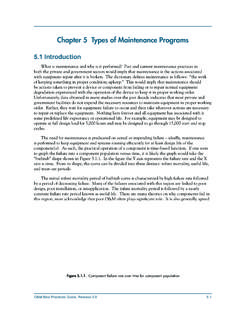
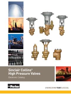
9 Of the load to outer layers This is based on outer layer fiber cost being 80% of inner layer fiber cost Development of lower cost standard modulus (~30 Msi) fiber could make this concept more effective13 Alternative fibers to Carbon Evaluate basalt fiber (produced from volcanic basalt mineral) as an alternative to Toray T700S14 FiberCost ($/lb) Design criteria not Design criteria not setBoron1, Design criteria not setSilicon Carbide4, Design criteria not setSaffilNo QuoteNo continuous tow availableCarbon 11 - f actor of saf e tyGl - factor of safety 0200400600800100012000102030405060708090 100 Tensile Modulus (msi)Tensile Strength (ksi)
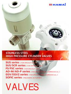
10 AluminuVectran MVectran HSPyronPyronS-glassE-GlassSpectraKevlarK evlar 49 ArimidTitaniumSteelZylon ASAS4T700T300JT300 PanexAS4T400 HAS2AS8 Zylon HMT1000T1000GT800M30IM7IM6IM9 InnegraM40JM5IM8M40M46M50M50JM66JM46JM60 JM35J1% Strain to Failure2% Strain to Failure4% 3% Strain to Failure5% Strain to FailureFiber PropertiesCarbon fiber, Glass, Aramid Basalt15 Chemical ResistanceSource: Kamenny Vek : Carbon fiber safety factor (SF) = , glass fiber SF = < Basalt SF < Modulus ResinPNNL s Approach and Technical Progress Predicted vessel burst Pressure by comparing two different resin systems Modeled cylindrical part of the vessel with ABAQUS and multiscale composites model, EMTA-NLA (Eshelby-Mori-Tanaka Approach for Non-Linear Analyses) Predicted burst Pressure is higherwith high modulus resin (Epoxy 2) Epoxy 2, P= MPaEpoxy 1, P= MPaBurstStrainsEpoxyPredicted Burst Pressure , MPa (ksi) ( ) ( )17~11% increase in predicted burst pressureNano-particle ResinSource.