Transcription of HIGH SPEED MACHINING (HSM) – THE EFFECTI VE WAY OF …
1 International Workshop CA Systems And Technologies - 72 - high SPEED MACHINING (HSM) THE EFFECTIVE WAY OF MODERN CUTTING Pasko, R. - Przybylski, L. & Slodki, B. Rafal Pasko Eng., Research assistant. Lucjan Przybylski Prof. Eng., Cracow University of Technology, Production Engineering Institute, Al. Jana Pawla II 37, 31-864 Cracow, Phone +48 12 648 01 30, Fax +48 12 648 20 10. Bogdan Slodki Eng., Cracow University of Technology, Production Engineering Institute. Summary: In this study the idea of HSM ( high SPEED MACHINING ) including some different definitions, is presented. The requirements referred to the machine tools, tools and MACHINING data are defined. Some examples of milling caves are described. Some economical advantages of productivity, accuracy in terms of tool and toolholder unbalancing are discussed. 1 Introduction MACHINING with high speeds (HSM) is one of the modern technologies, which in comparison with conventional cutting enables to increase efficiency, accuracy and quality of workpieces and at the some time to decrease costs and MACHINING time [9].
2 Even though high SPEED MACHINING is known for a long time (first tries were made in early twenties of the past century) there are still a lot of questions and less or more complicated definitions of HSM. The first definition of HSM was proposed by Carl Salomon in 1931. He has assumed that at a certain cutting SPEED which is 5 10 times higher then in conventional MACHINING , the chip tool interface temperature will start to decrease (Fig. 1). Fig 1. Temperature as a function of cutting SPEED [2, 9]. International Workshop CA Systems And Technologies - 73 - It is not possible to verify this theory to its full extent based on recent experimental results. There is a relative decrease of the temperature at the cutting edge that starts at certain cutting speeds for different materials. Actually there are many different ways to define HSM, upon them HSM is said to be [2]: ?
3 ? high cutting SPEED MACHINING (vc), ?? high rotational SPEED MACHINING (n), ?? high feed MACHINING (vf), ?? high SPEED and feed MACHINING , ?? high productive MACHINING . Practically, it can be noted that HSM is not simply high cutting SPEED . It should be regarded as a process where the operations are performed with very specific methods and production equipment [2]. HSM is not only MACHINING with high spindle SPEED because many applications are performed with conventional spindle speeds. HSM is often used in finishing in hardened steels with both high speeds and feeds. HSM can be called rather the high Productive MACHINING when MACHINING components in roughing to finishing and also in finishing to super-finishing in components of all sizes. 2 Applications of high SPEED MACHINING The use of HSM allow us to shorten the production time and to increase the accuracy of machined parts.
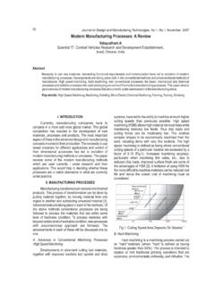
4 high SPEED MACHINING is being mainly used in three industry sectors due to their specific requirements [1]. Fig. 2. Improvement of production process when using HSM [2]. A) Traditional process. Non-hardened (soft) blank (1), roughing (2) and semi-finishing (3). Hardening to the final service condition (4). EDM process MACHINING of electrodes and EDM of small radii and corners at big depths (5). Finishing of parts of the cavity with good accessability (6). Manual finishing (7).B) Some process as (A) where the EDM-process has been replaced by finish MACHINING of the entire cavity with HSM (5). Reduction of one process step. C) The blank is hardened to the final service condition (1), roughing (2), semi-finishing (3) and finishing (4). HSM most often applied in all operations (especially in small sized tools). Reduction of two process steps. Normal time reduction compared with process (A) by approximately 30 50%. = Manual finishing International Workshop CA Systems And Technologies - 74 - The first category is industry which deals with MACHINING aluminum to produce automotive components, small computer parts or medical devices [1, 4, 10, 11].
5 This industry needs fast metal removal, because the technological process involves many MACHINING operations. The second category which is aircraft industry involves MACHINING of long aluminum parts, often with thin walls [1, 4, 10, 11]. The third industry sector is the die mould industry which requires dealing with finishing of hard materials [2]. In this category it is important to machine with high SPEED and to keep high accuracy. In this industry HSM is used for MACHINING such parts as [2]: Die casting dies. This is an area where HSM can be utilized in a productive way as most castings dies are made of demanding tool steels and have a moderate or small size. Forging dies. Most forging dies are suitable for HSM due to thir complex shape The surface is very hard and often prone cracks. Injection moulds and blow moulds are also suitable for HSM, because of their small sizes.
6 Which makes it economical to perform all operations in one set up. Milling of electrodes in graphite and cooper. It is an excellent area for HSM. Graphite can be machined in a productive way with Ti(C,N), or diamond coated solid carbide endmills. Modelling and prototyping of dies and moulds. is one of the earliest area for HSM. Easy to machine materials such as non-ferrous, for example aluminum are used. The cutting speeds are often as high as 15 000 50 000 [rpm] and the feeds are also very high . Using of the HSM in the above mentioned regions can cause the reduction of production process when electrode milling ECM and EDM . HSM ensres a dimensional tolerance of 0,02 mm, while the tolerance when using ECM is 0,1 0,2 [mm] and EDM 0,01 0,02. Replacing ECM with MACHINING causes the durability and tool life of the hardened die or mould is increased considerably.
7 3 Some recommended parameters for HSM There are some critical parameters for HSM, as for instance the depth of cut. The cutting tool manufacturers provide recommendations regarding the MACHINING parameters that should be used [7]. Those parameters are usually one of many operating windows [7] (applicable sets of parameters). An increase of cutting SPEED to HSM values give several benefits such as enlarging of the removal rate and improving of the final surface (Fig. 3). Fig. 3. Comparison of production indexes during MACHINING of a punch [3, 6, 8]. 12364,316,5120,333,505101520 Conventional milling, ball end mill, Dc=20 [mm], ap= [mm], vc=100 [m/min], fvz= [mm/tooth] HSM milling, ball endmill, Dc=20 [mm], ap= [mm], vc=900 [m/min], fz= [mm/tooth] 1 removal rate [cm3/min] 2 surface roughnessRa [?m] 3 polishing time [h] International Workshop CA Systems And Technologies - 75 - Below there is a comparison of speeds used during MACHINING some selected materials using conventional and HSM methods (Tab.)
8 1). Table 1. Conventional vs. high SPEED MACHINING [1]. Solid Tools (end mills, drills) WC, coated WC, PCD, ceramic Indexable Tools (shell mills, face mills) WC, ceramic, sialon, CBN, PCD Work material Typical cutting SPEED [m/min] high cutting SPEED [m/min] Typical cutting SPEED [m/min] high cutting SPEED [m/min] aluminum >305 (WC, PCD) >3050 (WC, PCD) >610 >3658 (WC, PCD) soft 152 366 366 1219 (sialon, ceramic) cast iron ductile 107 244 244 914 (ceramic) free mach. steel 107 366 366 610 alloy 76 244 213 366 stainless 107 152 152 274 steel hardness HRC65 24 122 30 (WC) 91 (CBN, ceramic) 46 (WC) 183 (CBN, ceramic) titanium 38 61 46 91 superalloy 46 76 84 (WC) 213 (sialon) 366 (sialon, ceramic) As it was pointed out before HSM is mainly used in die mold industry. Below some typical cutting data for MACHINING of die are selected in Tables 2 and 3. Table 2. Typical cutting data for solid carbide end mills with Ti(C,N) or TiAlN coating in hardened steel: (HRC 54 58) [2].
9 Type of processing vc [m/min] ap [%] * ae [%]* fz [mm/tooth] Roughing 100 6 8 35 40 0,05 0,1 Semi finishing 150 200 3 4 20 40 0,05 0,15 Finishing and Super-finishing 200 250 0,1 0,2** 0,1 0,2** 0,02 0,2 * % of the cutter diameter, ** [mm] Table 3. HSM cutting data by experience (R roughing, F finishing) [2]. vc [m/min] Material* Hardness Conv. HSM R HSM F Steel 150 HB <300 >400 <900 Steel 330 HB <200 >250 <600 Steel 300 HB <100 >200 <400 Steel 39 48 HRC <80 >150 <350 Steel 04 48 58 HRC <40 >100 <250 GCI 180 HB <300 >500 <3000 Aluminum 60 75 HB <1000 >2000 <5000 Non-ferr. 100 HB <300 >1000 <2000 * acording to Coromant Material Classification (CMC) International Workshop CA Systems And Technologies - 76 - During dry milling with those MACHINING parameters compressed air or oil mist under high pressure is recommended. 4 Toolholder and tool unbalancing problem The elements of the machine tool subsystem that determine efficiency of high SPEED MACHINING are: spindles, axes, motor drivers, toolholders and cutting tools.
10 The spindle is probably the most critical element [1], so to maintain maximum productivity and accuracy it is important to ensure the run-out as small as possible. The smaller the run-out is, the shorter is the time between changing inserts in a milling cuter. Especially in HSM applications the size of run-out is crucial for accuracy [1, 5]. The Total Indicator Readout (TIR ) should be maximum 10 microns at the cutting edge [2]. Every 10 microns in added run-out gives 50% reduction of tool life. Even if the tool, toolholder, and spindle are precisely balanced, there still can be several sources of instability. One of the sources of instability is the fit between toolholder and spindle interface. There is often a measurable clearance in this grip. Moreover, it also may be a chip or dirt inside the taper. In practice, an endmill run at 20 000 rpm may not need to be balance to any better than 20 gmm, and 5 gmm is generally appropriate for much higher speeds.