Transcription of High-Temperature Cathodic Disbondment Testing: …
1 2 FEBRUARY 2015 MATERIALS PERFORMANCE NACE INTERNATIONAL: VOL. 54, NO. 2 COATINGS & LININGSAC athodic Disbondment testing has historically been performed on protec-tive coatings to assess coating delami-nation resistance when exposed to Cathodic polarization. Unfortunately, there is no broadly accepted high -tem-perature Cathodic Disbondment testing standard in the pipeline industry. Fac-tors that affect the High-Temperature Cathodic Disbondment test be havior of fusion-bonded epoxy-based coat ings are reported, as well as the results of a global survey on laboratory test prac-tices. Part 2 of this article, to be pub-lished in March 2015 M P, will discuss a program that tested the Cathodic dis-bondment of an actual pipe explorations and production for oil and gas reservoirs go deeper and fluid tem-peratures get hotter, there are new demands to fill the gap for test methods to evaluate High-Temperature Cathodic Disbondment performance of pipeline coating systems.
2 Pipe coating materials/products for High-Temperature applications, such as High-Temperature fusion-bonded epoxy (FBE) powders, are relatively new to the industry. The great majority of conventional FBE powders developed prior to 2000 have a glass transition temperature (Tg) of ~100 C, and the usual maximum operating temper-ature specified for conventional standalone FBE is 60 C. The commonly recommended maximum operating temperatures for stan-dard three-layer polyethylene (3 LPE) sys-tems and standard three-layer polypropyl-ene (3 LPP) systems are 85 and 110 C, respectively. Only recently have coating manufacturers developed high -Tg FBE coat-ings that are also recommended as a primer for multilayered PP systems at tempera-tures >110 C. The pipeline industry is cur-rently discussing relevant standards and testing techniques to qualify high -tempera-ture FBE and PP coating products for oper-ating temperatures of 150 C and higher.
3 Review: Factors Affecting High-Temperature Cathodic DisbondmentFactors affecting Cathodic disbond-ment behavior of a coating have been ex-tensively studied and reported, and these factors are considered in many reviews by NACE International Technology Exchange Group (TEG) 349X and Task Group (TG) 470 of existing international standard ca-thodic Disbondment test Some critical factors, which are more specific to High-Temperature Cathodic Disbondment behavior, include the Effect and Anode Isolation Chemical attack of the coating during Cathodic Disbondment testing can be caused by the formation of hypochlorite or chlorate(I) anions (ClO ), resulting in coat-ing deterioration/delamination that is quite different from Cathodic The hypochlorite effect is more High-Temperature Cathodic Disbondment testing : Review and Survey Part 1 Shiwei william Guan, Bredero Shaw, SingaporeJ. alan Kehr, Alan Kehr Anti-Corrosion, LLC (AKAC), Lakeway, Texas3 NACE INTERNATIONAL: VOL.
4 54, NO. 2 MATERIALS PERFORMANCE FEBRUARY 2015significant at higher temperatures . This phe-nomenon does not occur in the field because the anode and cathode are far apart and do not produce hypochlorite. An anode isolation scheme can prevent anolyte chlorine gases from migrating to the Cathodic sites to form hypochlorite during testing . Historically, the majority of Cathodic Disbondment testing data have been ob-tained without anode isolation. Recent re-search by Al-Borno4 found that the use of anode isolation causes the pH value of the Cathodic Disbondment test environment to be significantly higher as early as the first 24 h, but Disbondment is also reduced. This contradicts the pH effect revealed in earlier studies by Rodriguez,5 which suggest that highly alkaline solutions penetrate further than neutral solutions into the crevice formed by a disbonded FBE coating. This added penetration produces more Disbondment by affecting the coating-to-sub-strate interaction and displacing the coating.
5 Al-Borno6 also suggests that greater disbond-ment without anode isolation is an indication that the hypochlorite effect is more signifi-cant than the pH effect in increasing disbond-ment; however, this work only reports results of Cathodic Disbondment tests conducted for 72 h and 28 days. It is possible that an ex-tended test duration will allow the build-up of hypochlorite to become more significant than the pH effect that initially dominates. The implementation of anode isolation may result in significantly different disbond-ment results compared to existing tests. In-troduction of this variable requires an evalu-ation of the resulting data before setting Cathodic Disbondment acceptance criteria. J. Holub2 suggests the use of anode isolation, frequent electrolyte refreshment, and proper selection of the electrolyte temperature to avoid coating delamination due to chemical attack. These modifications may invalidate most historical data when establishing a suf-ficiently large database.
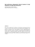
6 Specimen Geometry and Preparation Before and After Cathodic Disbondment TestAlthough it was found that Cathodic dis-bondment test specimen geometry, whether FIGURE 1 A thick 3 LPP sample after Cathodic Disbondment testing for 48 h at V and 95 2 Removing the outer layer after Cathodic Disbondment testing could damage the 1. HEATING PROFILES OF A SUBMERGED ARC-WELDED DUPLEX STEEL PIPE DURING THE FBE COATING PROCESSL ocationSurface Temperature, T ( C)Lead endOn body242 C < T < 246 CWeld-seam210 C < T < 225 CMiddleOn body241 C < T < 246 CWeld-seam184 C < T < 210 CTrail endOn body239 C < T < 246 CWeld-seam184 C < T < 210 Cflat, a curved steel panel, or a tube, had no impact on Cathodic Disbondment test re-sults,3 it is practical to use only full ring tube specimens for pipe sizes <16 in (406 mm) in diameter. Cut panels or quarter ring/half shell tubes should only be consid-ered for specimens from pipes that are >20 in (508 mm) in diameter.
7 Pipe ring speci-mens should be at least 12-in (305-mm) long with the test area >6 in (152 mm) from the cut onshore FBE/three layer polyolefin (3 LPO) pipeline coatings are often to 3-mm thick, and do not require spe-cial specimen preparation. For onshore hori-zontal directional drilling (HDD) or offshore insulation applications, the pipeline coating can be hundreds of millimeters thick. Ca-thodic Disbondment tests on such thick coatings often yield meaningless results with little or no Disbondment . Sometimes making the radial cuts and lifting the dis-bonded coating with a knife is not possible (Figure 1). One solution is to machine thick, rigid coatings to a thickness no greater than 3 mm before Cathodic Disbondment testing . Some standards/specifications (such as NFA 49-7117) assess the Cathodic Disbondment after heating the 3 LPO coating in a furnace to soften the adhesive layer, and detaching the top layer (Figure 2).
8 Excessive heating, however, has the potential of damaging the FBE during the removal Epoxy Film ThicknessFBE film thickness plays an important role in Cathodic Disbondment resistance: a thicker coating typically shows less dis-bondment. This is of practical importance because some specifications request a ca-thodic Disbondment test on the primer 4 FEBRUARY 2015 MATERIALS PERFORMANCE NACE INTERNATIONAL: VOL. 54, NO. 2 COATINGS & LININGS alone. FBE as a primer for three-layer coat-ings has a thickness that is normally sig-nificantly lower than the thickness of FBE as a standalone coating. Application tem-perature and quenching effects are often significantly different between multilayer polyolefin coatings and standalone FBE. These factors can result in significantly dif-ferent results. The acceptance criteria need to be TypesThe effect of steel type on performance testing of an FBE-based pipeline coating has rarely been studied because existing pipelines usually are low-carbon mild steel.
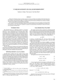
9 The pipeline industry now uses different types of steel, such as high -strength steel (X80 to X120), duplex and stainless steel, and corrosion-resistant alloys that are me-chanically or metallurgically clad to pipes. These special types of steel tend to behave quite differently during the FBE application process. For example, grit blasting different types of steel results in different anchor patterns, which can affect Cathodic dis-bondment results. Table 1 illustrates variations in a pipe preheating temperature profile of a ~16-in (408-mm) diameter submerged arc-welded duplex steel pipe after going through in-duction coils at a line speed of ft/min (4 m/min) and prior to FBE application. The surface temperatures on the pipe body and along/near the weld seam area were FIGURE 3 A FBE sample after Cathodic Disbondment testing for 28 days at V and 65 C (holiday depth = mm).FIGURE 4 A FBE sample after Cathodic Disbondment testing for 28 days at V and 65 C (holiday depth = mm).
10 Significantly different, with a change in temperature of up to 40 C. The root cause is that the weld seam and the pipe body of a submerged arc-welded duplex steel pipe have different ferritic-austenitic structures and ferrite contents, which do not respond uniformly to the electro-magnetic induc-tion heating during the coating DepthTo set up a typical Cathodic disbond-ment test, an artificial holiday, 6 mm in size, shall be drilled with a flat head end mill bit and penetrate < mm into the steel. Figures 3 and 4 illustrate the results of a 28-day Cathodic Disbondment test at V and 65 C for two FBE production qualification trial samples with the same production conditions. Only the holiday depths were different. No differences in ca-thodic Disbondment results were found after 48 h at V and 65 C. Compared with Figure 3 (with a holiday depth of mm and average Cathodic Disbondment of mm), Figure 4 (with a holiday depth of mm and average Cathodic disbond-ment of mm) shows darker and more scattered rust marks on the larger dis-bonded surface.