Transcription of High Voltage AC Induction Motors - Marathon …
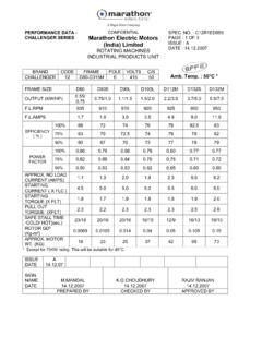
1 A REGAL-BELOIT COMPANYM otors for the Long Run! high Voltage ACInduction high Voltage and core, shaft andshaft-mounted and heat , rating and general of markings, directionof rotation and and Impak range has been designed to provide the maximumvariety of cooling forms and enclosures, whilst still utilisingstandardised electrical stator frames have been developed for each frame size: a horizontal foot mounting frame, mounting designationIM 1001, and a vertical flange/skirt mounting frame,mounting designations IM3011 horizontal foot mounting frame has an open top withImpak high Voltage rangeFrames 355, 400 & 450machined faces to accept the cover or heat exchanger. Thevertical flange/skirt mounting frame has two open sideswith similarly machined specified range of cooling forms and enclosures isavailable on each mounting first part of this publication details the mechanicalfeatures while the second part deals with 1. Horizontal Mounting HT Motor3 Standards and specificationsPerformanceStandard Impak Induction Motors comply with requirementsof B-1 and with BS 4999-Part 4, 30, 31, 42, 50, 51, 60,61, 69 and 72 and Indian Standard IS 325, 8223, 4829and other relevant Indian Standard for Variable Speed Drive (VSD) applications arealso 2.
2 Vertical Mounting HT dataStandards & specifications ofmechanical features :Degrees of protection by enclosureDegrees of protection available conform to requirements ofIEC 34-5, BS 4999-Part 20, 1972 and Indian Standard IS4691 and other relevant Indian Standard standard degrees of protection are IP 54 & IP , if required, we can offer machines with IP 23degree of Impak range has been designed to provide the maximumvariety of cooling forms and enclosures, whilst still utilizingstandardised electrical FormsCooling arrangements are in accordance with IEC-34-6and BS 4999 Part standard cooling form for machines with degrees ofprotection IP 20 to IP 23 is enclosed ventilated IC 01. Thisis achieved by use of a shaft mounted fan with free air inletand a machine with degree of protection IP-44 or IP 55 theusual cooling arrangement is totally enclosed fan ventilatedIC 0161, utilizing an independent machine mounted heatexchanger and shaft mounted fans. Motors with forcecooling system are also designations are in line with IEC-34-7 Code 11and BS 4999 Part 22 Code standard arrangements available are horizontal footmounting IM 1001 and vertical flange mounting IM horizontal foot mounting frame has an open top andvertical machine has two open sides.
3 All such faces aremachined to accept heat exchanger or and fixing dimensions are to BS 3979 and BS 4999 Part 10 or IS 8223-1976. The recommendation of IEC-72and IEC-72A can also be 1. The degrees of protectionThe codings offer protection againstIP20 Contact with live ormoving parts by objects with diameters of12mm and aboveIP22 Ingress of foreign bodiesHarmful effects of water falling-do-with diameters of 12mm andat any angle up to 15 fromabovethe verticalIP23 Harmful effects of water falling-do--do-as a spray at an angle equal toor smaller than, 60 with respectto the verticalIP44 Contact with live orIngress of foreign bodiesHarmful effects of water splashedmoving parts by objectswith diameters of 1mmagainst the motor from anyof 1mm thicknessand abovedirectionIP54 Contact with live orIngress of harmful deposits of dustHarmful effects of watermoving parts (complete)to an amount inconsistentsplashed against the motorprotection)with correct operationfrom any directionIP55 Harmful effects of water-do--do-projected by a nozzle againstthe motor from any directionTable 2.
4 Cooling formsOneIC01 OpenShaft-mounted fan only, Free inlet and outlet(primary)coolingcircuitTwo(primary /IC0161 ClosedIndependent machine-mounted heat exchangersecondary)Shaft-mounted constructionStator constructionStator FrameHorizontal Mounting MachinesThe stator frames are of cast iron / fabricated steelconstruction with an open flat top and terminal outlet oneach side. The side walls are recessed to accommodate thesocket head screws that secure the various alternative ribbing provides high structural strength. Registersto accept and spigotted bearing brackets are machinedinto the frame. Feet and lifting eyebolt bosses are castintegral with the Mounting MachinesStator frames for vertically mounted machines are similarin design to those for horizontally mounted machines butcertain frames are offered with a fabricated steel frames for both horizontal and vertical mountingmachines have a smooth wipe-down exterior with cleanmodern Motors are generally manufactured by using cold rollednon-grain oriented low loss steel sheet.
5 This results in abetter and efficient machine of low weight and 3. The stator frame of a horizontal mounting Impakmotor showing the strong internal 4. The stator frame of a vertical mounting motor showingthe similarity of internal construction to the horizontalmounting coreThe machines have laminations built into them located bya key, compressed between steel endplates and locked inposition by a steel key Brackets (End shields)Bearing brackets on most machines are produced from thesame grade of cast iron as employed for the stator vertical machines designed to accommodate highthrust forces have fabricated steel bearing brackets have a machined spigot to locate intothe stator frame and ensure concentricity. Brackets aresecured by steel machines with grease-lubricatedrolling bearings have expelled grease trays manufacturedfrom extruded aluminium or if specified, steel, mounted onthe bearing foot mounting machineStandard rolling bearings, grease-lubricatedThis is the standard arrangement for all but 2-pole 400 and450 frames operating on a 50/60 Hz metric dimensioned rolling bearings are mounteddirectly into bores in the bearing endbrackets.
6 Inner bearingraces are locked onto the shaft by shaftnuts and grub bearing caps of cast iron position the outer races andare also used during dismantling as bearing extractors forthe full caps of cast iron prevent axial movement of thebearing and contain a weather sealing arrangement asstandard. Dust-protecting outer caps are available to nipples are provided for lubricating the bearingswith the motor either stationary or pressure relief system embodying a rotating grease valveis included as the means of grease removal devices fitted to the end-brackets, surplus grease ejected from the bearings can beremoved whilst the motor is either stationary or expelled grease trays are manufactured from extrudedaluminium or, if specified, 6. View of an Impak showing the lubrication point,expelled grease tray (in the open position) and dust-protecting outer bearing 7. Shaft-mounted components. The inner greaseflinger/seal is an interference fit on the shaft. The outerwater flinger/grease seal is secured to the shaft by a 5.
7 The arrangement of the grease-lubricated rollingbearings. The grease enters the bearing from the outboardside and surplus grease is ejected by the pointBearingouter capWeatherproofing O ringShaft andshaft-mountedcomponentsWater flinger/grease sealGrease removalchannelGrease discharge ductInnergreaseflinger/sealBearinginner capMotorend bracket7 Top bearingThe top bearing arrangement supports the weight of themotor and any external axial thrust within the standard arrangements are of either the four pointcontact ball or tapper roller flange/vertical skirt mounting machinesThe choice depends upon the lubrication requirementscorresponding to the motor speed and the amount of axialthrust that has to be supported. With both bearingarrangements axial thrust can be accommodated in eitheror both is the standard arrangement for 355 and 400, 4 to12 pole, and 450, 6 to 12 pole, Motors operating on a 50Hz supply and all 8 to 12 pole Motors operating on a 60Hz metric dimensioned rolling bearings are mounteddirectly into bores in the cast iron or steel endbrackets.
8 Innerbearing caps are of cast iron. Inner bearing races arelocked onto the shaft by shaftnuts and bearing enclosure is weather-protected and a pressurerelief system embodying a rotating grease valve is includedas standard. Dust-protecting outer caps are available tospecial order. Grease nipples are provided for lubricatingthe bearings with the motor stationary or rotating. A shaft-mounted grease flinger transfers surplus grease to a chamberwhich should be cleaned out point contact ball bearing grease-lubricatedFig. 8. A typical four point contact ball bearing arrangement on 9. Typical drive end bearing arrangement of BEARING CAPROLLER BEARINGOUTER BEARING CAPSHAFTOUTER LABYRINTHDRIVE ENDBRACKETINNER LABYRINTH8 Bottom bearingRoller bearings grease lubricatedThis is the standard arrangement for 355, 2 to 12 pole,and 355, 400 & 450, 4 to 12 pole Motors , operating oneither a 50 or 60 Hz metric dimensioned bearings are mounted directly intobores in the cast iron bearing caps of cast iron position the outer caps of cast iron prevent axial movement of thebearing and contain a weather sealing arrangement asstandard.
9 Dust-protecting outer caps are available to nipples are provided for lubricating the bearingswith the motor either stationary or running. A pressure reliefsystem embodying a rotating grease valve is included grease is stored in a chamber which should becleaned out 11. A typical grease-lubricated roller bearing 10 Close-up of the lubrication point for grease-lubricatedroller bearings on a vertical flange mounting LubricationThe tables given below show the bearing sizes lubricatinginterval and quantity of grease required for standardmachines. However in special applications differentbearings/bearing arrangements can also be 3 Bearing size, lubricating interval and grease capacity of horizontal foot mounted IM 1001, CACA, IP 44, 54 & SPDP,IP 22, 23 motor (up to kV)Bearing DetailsQuantity of lubricantsLubricatingFramePoleDriving end Non-driving endDriving endNon-driving endInterval(Roller bearing)(Ball bearingcmcm(Running) (hours)D3554N base grease to be used 3 of Bharat Petroleum, Servogem 3 of or greasing is not 4 Bearing size, lubricating interval and grease capacity of vertical flange/skirt mounted IM 3011/IM 3811, IP 44, 54,22, 23 (up to kV) MotorBearing DetailsQuantity of lubricantsLubricatingFramePoleDriving end Non-driving endDriving endNon-driving endInterval(Roller bearing)(Ball bearingcmcm(Running) (hours)))
10 3554N 321QJ 3202100210040006-12N 321QJ 3202100210080004004N324QJ 3202500210040006-12N 324QJ 3202500250080004506-12N324QJ base grease to be used 3 of Bharat Petroleum, Servogem 3 of or greasing is not CoreThe rotor core is built u-p of laminations on the shaft witha light interference fit and positioned by a key. Thelaminations are compressed between steel endplates andlocked by a steel key ring or nut. The winding comprisescopper strips brazed to endrings for squirrel cage rotorand TIG Welded with relevant bar using a C -clip for slipring are designed to eliminate the risk of fatigue or otherfailures. Standard material is carbon/manganese steel ofsuitable grade. We normally use forged bar as shaft extension lengths and diameters have been specifiedin respective dimensional drawings. However, differentextension lengths can also be offered. The shaft end canbe tapped with one or two holes for are single round-end parallel run out as FanThe internal fan is fabricated from sheet and added to asteel hub.