Transcription of Hollow-core slabs with cast-in-place concrete toppings: A ...
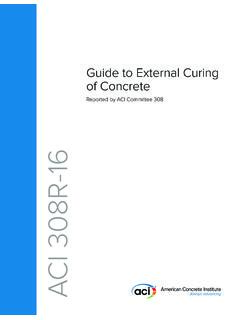
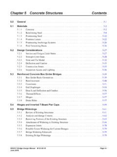
1 Summer 2013 | PCI Journal124 Since the 1950s, prestressed concrete Hollow-core slabs have been used in a variety of structural ap-plications, including residential and commercial buildings, parking structures, and short-span bridges. The slabs contain voids that run continuously along their length, which helps reduce dead weight and material cost. Figure 1 shows Hollow-core slabs with two different top surface slabs are economical, have good fire resis-tance and sound insulation properties, and are capable of spanning long distances with relatively shallow depths. Common depths of prestressed Hollow-core slabs range from 6 to 10 in. (150 to 250 mm) for spans of approxi-mately 30 ft (9 m). More recently, Hollow-core slabs with depths as great as 16 in. (410 mm) have become available and are capable of spanning more than 50 ft (15 m).In practice, a concrete topping layer is often cast in place onto the top surface of Hollow-core slabs to create a contin-uous level finished surface.
2 The topping layer is typically 2 in. (50 mm) deep. The topping may increase the flexural strength, shear strength, and bending stiffness of the slab if composite action is developed with the Hollow-core action between the cast-in-place concrete topping and the Hollow-core unit is developed primar-ily through bond at the interface. Steel reinforcement to promote composite action across concretes cast at differ- This paper reports tests on two types of Hollow-core units (dry mix and wet mix) to determine the interfacial shear strength between them and their cast-in-place concrete toppings. Tests conducted using push-off specimens designed to gener-ate shear stresses at the interface showed that interfacial shear strength correlates with surface roughness, sandblasting to remove laitance (from wet-mix specimens), and slabs with cast-in-place concrete toppings: A study of interfacial shear strengthRyan M.
3 Mones and Sergio F. Bre a125 PCI Journal | Summer 2013data in this programTwenty-four specimens representing two different meth-ods of Hollow-core slab production were tested. The two producers that fabricated the Hollow-core units use differ-ent fabrication machines and therefore employ different concrete mixtures in their processes. One producer uses an extruder with a dry-mix concrete , and the other uses a slip form machine with a wet-mix concrete . These two types were selected to broaden the applicability of the research results. The laboratory specimens were constructed using short segments of Hollow-core units onto which a cast-in-place concrete block representing the topping concrete was placed. The Hollow-core units were fabricated with differ-ent surface conditions to determine the influence of surface roughness on interface shear descriptionTesting was conducted on push-off specimens consisting of two blocks of concrete cast at different times.
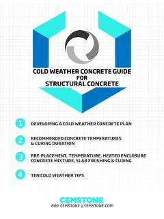
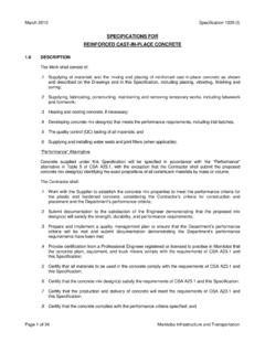
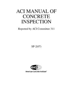
4 The bottom block, a 36 in. (910 mm) long Hollow-core segment, was fabricated in a Hollow-core producer facility and shipped to the laboratory. The top block was cast in the laboratory directly on the bottom block using a concrete strength that would typically be encountered in toppings. Figure 2 shows specimen geometry and push-off specimens were designed to ensure that ap-plied loads only generated shear stresses along the surface between bottom and top blocks without creating any nor-mal stresses. Therefore, the top block had to be cast into an L-shape and a structural steel assembly was embedded into the bottom block at the fabrication facility (Fig. 3). ent times is not practical for this application because of the automated fabrication process of Hollow-core units. Interface shear strength may potentially be increased by roughening the precast concrete surface before placement of the topping.
5 The American concrete Institute s Building Code Requirements for Structural concrete (ACI 318-11) and Commentary (ACI 318R-11)1 currently limits the de-sign horizontal shear strength of unreinforced, intentionally roughened composite interfaces to a maximum of 80 psi ( MPa) but fails to define what constitutes an intention-ally roughened surface. Section of the PCI Design Handbook: Precast and Prestressed Concrete2 states that experience and testing indicate that normal finishing meth-ods used for precast concrete surfaces may be considered as intentionally roughened surfaces for design objective of this research was to investigate the influ-ence of surface preparation techniques on interface shear strength between Hollow-core slabs and cast-in-place con-crete toppings. With a better estimate of interfacial shear strength, the flexural and shear strength benefits associated with composite action between Hollow-core units and cast-in-place concrete toppings could be exploited.
6 Only those techniques that were practically feasible were included in this study, though several are not commonly performed. Several past studies3 6 have focused on determining the interfacial shear strength of concrete cast at different times and having different surface roughnesses, with and without transverse reinforcement crossing the interface. Previ-ous researchers have also tested Hollow-core slabs with composite topping,7 9 but the primary focus of these studies has been to determine the flexural and shear strength of the composite units. Past researchers have not specifically focused on the interfacial shear strength between Hollow-core units and cast-in-place concrete toppings, with the units fabricated using typical producer practices. The main goal of this research project was to provide experimental Figure 1. Hollow-core with machine-finished surfaceLongitudinally raked slabSummer 2013 | PCI Journal126 Table 1 lists the finishing process used on the top surface of the bottom blocks.
7 Top surface conditions in-cluded machine-finished surfaces, longitudinally raked surfaces, longitudinally or transversely broomed surfac-es, and sandblasted surfaces, with grout added to some of those surfaces (Fig. 4). Duplicate bottom blocks were fabricated and tested for each surface condition. Surface roughening was performed at the Hollow-core fabrica-tion plant. Grout was applied onto the test region of The test region of the specimens consisted of a 15 15 in. (380 380 mm) surface in the central region of the contact area between the top and bottom blocks. This test region is smaller than the total contact area between blocks (Fig. 2). The contact surface outside of the test region was intentionally debonded using plastic and smooth tape. The geometry of the top block was designed to ensure that the top block weight would not generate significant normal stresses on the test area. Figure 2.
8 Dimensions of push-off specimens and instrumentation location. Note: 1 in. = 3. Views of bottom and top blocks in steel assembly insert in dry-mix longitudinally raked specimen DRY-LRX-1 Side view of specimen before testing127 PCI Journal | Summer 2013finishing. Machine-finished specimens therefore capture roughness conditions that are typical of the two Hollow-core production methods investigated and properties of the concrete mixture. The surface of the dry-mix longi-tudinally raked specimens was roughened using a rake attached to the Hollow-core extruder that was dragged along the surface before concrete setting. All other roughened specimens were roughened by dry-mix bottom blocks were cast on the same day using the same batch of concrete . Most wet-mix bot-tom blocks were also cast on a single day using a single batch except for wet-mix longitudinally broomed speci-men WET-LBX-2, which was cast one week specimens for each of the two fabrication processes (wet-mix and dry-mix).
9 Only specimens with machine-finished and longitudinally roughened surfaces were selected for grout application. In grouted specimens, a commercial nonshrink sand-cement grout was applied in a layer approximately 1/16 in. ( mm) thick in the laboratory using a steel trowel and roughened using a stiff broom. The grout was allowed to dry 24 to 48 hours before casting the top block. Pressurized air was used to remove loose particles from the top surface of the bot-tom block before application of top surface of machine-finished specimens remained as produced by the fabrication machine without further Table 1. Specimen labels, concrete material strengths, and surface roughness measurementsSpecimen labelSurface conditionTop block compressive strength, psiTop block splitting tensile strength, psiBottom block compressive strength, psiDRY-MFX-1 Machine finished46704206920 DRY-MFX-237803607170 DRY-SBX-1 Sandblasted45104107310 DRY-SBX-250004407740 DRY-LRX-1 Longitudinally raked46304207600 DRY-LRX-250204508010 DRY-TBX-1 Transversely broomed47504507450 DRY-TBX-251404807880 DRY-MFG-1 Machine finished, grouted46704108150 DRY-MFG-250504408430 DRY-LRG-1 Longitudinally raked, grouted48204508290 DRY-LRG-251104408580 WET-MFX-1 Machine finished51804409700 WET-MFX-251804509730 WET-SBX-1 Sandblasted49604309750 WET-SBX-245304409760 WET-LBX-1 Longitudinally broomed51904509720 WET-LBX-248104109780 WET-TBX-1 Transversely broomed49304109810 WET-TBX-241404709830 WET-MFG-1 Machine finished.
10 Grouted43104209850 WET-MFG-254204209880 WET-LBG-1 Longitudinally broomed, grouted45103809900 WET-LBG-241003709920 Note: 1 psi = 2013 | PCI Journal128 MaterialsTo avoid damaging the interface during handling in the laboratory, the top blocks were cast after the bottom blocks were positioned in the testing frame. The top blocks were fabricated using concrete with a design compressive strength of 4000 psi ( MPa). The top block concrete mixture had a maximum aggregate size of 3/8 in. (10 mm) that reflects characteristics of common topping concrete mixtures. The day before placing the top block concrete , the surface of the bottom block was saturated with water. Standing water was blotted dry prior to placing concrete . Mechanical vibration was used to compact the top block concrete after placement. The top block was cured at room temperature (approximately 70 F [20 C]) with wet burlap and plastic for 48 hours after casting.