Transcription of HOLLOW STRUCTURAL SECTIONS - Bull Moose Tube
1 HOLLOW . STRUCTURAL . SECTIONS . Beam Load Tables OF NORTH AMERICA. 1 9 9 8 R E V I S E D E D I T I O N. HSS Manufacturing Methods The transformation of steel strip into HOLLOW STRUCTURAL SECTIONS (HSS) is the result of operations including forming, welding and sizing. Currently three methods are being used in North America for the manufacture of HSS. These methods, including two ERW methods and an SAW method, are described below. Both ERW methods meet ASTM A 500 and CSA requirements for the manufacture of HSS, and the ERW sizes included in this publication may be produced to either standard. The SAW method is not included as a manufacturing process in the ASTM or CSA specification. SAW sizes listed in this publication can be specified to meet desired physical and dimensional criteria of ASTM.
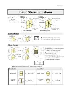
2 A500 and CSA Electric Resistance Welding (ERW) Process 5 6 7. 4. In the tube mill, flat steel strip (1) is formed continuously around its 3. longitudinal axis to produce a round tube. This is done by moving the 2. 1. strip through a progressive set of rolls (2-6). The strip edges (7) are heated by either high frequency induction or contact welding and then forged together by weld rolls to create a continuous longitudinal weld 8. without the addition of filler metal. The weld seam (8) is then cooled and processed through a set of sizing/shaping rolls which cold-form it into a round (9), square (10) or rectangular (11) section . 9 10 11. Form-Square Weld-Square (ERW) Process In the weld mill, driven forming dies progressively shape the flat strip (1) by forming the top two corners (2) of the square or rectangular tube in the initial forming station.
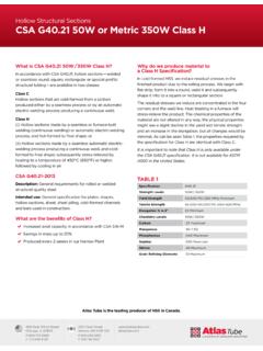
3 Subsequent stations form the bottom two corners (3) of the shape. No cold working of the sides of the shape is 4. performed, and the shape's seam is welded by high-frequency contacts when the tube is near its final shape and size. The welded tube (4) is 1 2 3 3 2 1. cooled and then driven through a series of sizing stations which qualifies the tube's final dimensions. Submerged Arc Weld (SAW) Process Two identical pieces of flat strip (1) are placed in a press brake and formed into two identical halves (2) of a finished tube size. A backup bar is tack welded to each leg of one of the half- SECTIONS (3). The two half- SECTIONS are fitted together toe-to-toe (4) and welded by the submerged 5. arc process to complete the square or rectangular section (5).
4 1 2 3 4 2 1. 2. Foreword Tables of allowable uniformly distributed loads are presented for rectangular and square HOLLOW structur- al SECTIONS (HSS) manufactured by the electric resistance welding (ERW) and the submerged arc welding (SAW) processes. Tables of maximum unbraced compression flange lengths and tables of midspan deflec- tions for uniformly loaded simple span beams are also included. The tables of allowable uniformly distributed loads have been calculated in accordance with the 1989. Specification for STRUCTURAL Steel Buildings - Allowable Stress Design and Plastic Design published by the American Institute of Steel Construction. The allowable uniformly distributed loads are based upon section property data for HSS that were recalculated in 1996 to account for today's more precise manufacturing methods.
5 The recalculated section property data for HSS are published in HOLLOW STRUCTURAL SECTIONS - Dimensions and section Properties available from the Steel Tube Institute of North America. Tables are presented for two specified minimum yield stress steels - Fy = 46 ksi and Fy = 50 ksi. Allowable uniform loads for HSS sizes produced by the ERW and SAW manufacturing methods are pre- sented in separate tables. The allowable uniformly distributed loads are based upon the allowable bending stress, Fb, equal to and The allowable uniformly distributed loads for slender SECTIONS are calculated in accor- dance with AISC Specification Appendix B. Slender SECTIONS are indicated in the tables with an asterisk (*) immediately following the design wall thickness parameter and a double asterisk (**) immediately following the modified value of Sx.
6 The tabulated loads include the weight of the HSS beam which must be deducted to determine the net load that the beam will support. It is assumed that the load is applied in the plane of the minor axis and that the HSS beam deflects vertically in the plane of bending only. Deflections corresponding to the tabulated loads are also given. Deflections caused by actual loading less than the full allowable load may be obtained by multiplying the tabulated deflection by the ratio of the actual load to the tabulated allowable uniform load. Tabulated values of maximum laterally unsupported lengths, Lc, of compression flanges of HSS beams from 1 1/4 inches through 32 inches in width and for varying ratios of M1/M2 are presented for Fy = 46 ksi and Fy = 50 ksi specified minimum yield stress steels - see page xx and page xx.
7 The Lc values are calculat- ed in accordance with AISC Specification SECTIONS B5 and F3 which specify that the laterally unsupported length of the compression flange of an HSS beam for which the allowable bending stress may be taken at shall not exceed the value except that it need not be less than 1200(b/Fy). ( 1950+1200. M1. M2 ) b Fy Refer to Part 2, Beam and Girder Design, in the AISC 9th edition Manual of Steel Construction for a discussion of lateral support of beams, beams with concentrated loads and vertical deflection. Symbols used in these tables follow those used in the AISC Manual . Tables of deflections for fully stressed, uniformly loaded simple beams from 1 1/4 inches through 32. inches in depth and for varying span lengths are also included.
8 These tables are presented for allowable bending stresses equal to 33 ksi ( x 50 ksi), ksi ( x 50 ksi) and ksi ( x 46 ksi) - see pages xx - yy. Deflections for allowable bending stress equal to ksi ( x 46 ksi) can be obtained by adding approximately 1 % to the deflection values presented in the table for allowable bending stress equal to ksi. 4. Table of Contents Page How to Use the Beam Load Tables 6. Lc Tables 7. Beam Load Tables Rectangular HSS (ERW) Fy = 46 ksi 8. Square HSS (ERW) Fy = 46 ksi 38. Rectangular HSS (ERW) Fy = 50 ksi 50. Square HSS (ERW) Fy = 50 ksi 80. Rectangular HSS (SAW) Fy = 46 ksi 92. Square HSS (SAW) Fy = 46 ksi 98. Rectangular HSS (SAW) Fy = 50 ksi 102. Square HSS (SAW) Fy = 50 ksi 108. Deflection Tables 113.
9 The information presented in this publication has been prepared in accordance with recognized engineering principles and is for general information it is believed to be accurate, this information should not be used or relied upon for any specific application without competent professional examination and verification of its accuracy, suitability, and applicability by a licensed professional engineer, designer, or publication of the material contained herein is not intended as a representation or warranty on the part of The Steel Tube Institute of North America or of any other person named herein, that this information is suitable for any general or particular use or of freedom from infringement of any patent or patents.
10 Anyone making use of this information assumes all liability arising from such use. Caution must be exercised when relying upon other specifications and codes developed by other bodies and incorporated by reference herein since such material may be modified or amended from time to time subsequent to the printing of this Institute bears no responsibility for such material other than to refer to it and incorporate it by reference at the time of the initial publication of this edition. How To Use The Beam Load Tables Example I Example III. A simply supported 8 in. x 4 in. x 1/4 in. ERW HSS beam of Select the lightest 7-inch deep, simply supported ERW HSS beam of Fy = 46 ksi (ASTM A500 Gr. B) spans 16 feet. The compression Fy = 50 ksi (ASTM A500 Gr.)