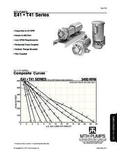
Transcription of HORIZONTAL CLOSE COUPLED VERTICAL FLANGE …
1 Section E41 T41 Page 501 Dated June 201697-4622-01-588E41 T41 SERIESPump ManualHORIZONTAL CLOSE COUPLEDVERTICAL FLANGE MOUNTEDFLEXIBLE COUPLEDS ection E41 T41 Page 502 Dated June 201697-4622-01-588E41 T41 SERIESHORIZONTAL CLOSE COUPLED PUMPSVERTICAL FLANGE mounted CLOSE COUPLED PUMPSFLEXIBLE COUPLED InstructionsA. Inspection of EquipmentB. StorageC. Placing Stored Pumps Into ServiceD. Application ConsiderationsE. Recommended Spare PartsWhen properly installed and given reasonable care and maintenance, regenerative turbine pumps should operate satisfactorily for many years. Because of the high differential pres-sures expected in a regenerative turbine pump, CLOSE running clear-ances are used to reduce internal losses. Abrasive particles, even microscopic ones, in high enough concentrations, can open up the CLOSE clearances between internal components. For critical services it is recommended that you keep an identical pump for stand-by Inspection of EquipmentImmediately upon receipt of the shipment, inspect the equipment for damage or missing components.
2 Check the shipping manifest and report any damage or shortage to the Transportation Company s local agent. Inspect the crate and any wrapping material before discarding. Parts or accessories are sometimes wrapped individually or fastened to the skid. Put the instructions that came with the shipment in a safe place where they will be available to those who will be using them for installation and StorageIf the pump is to be stored before use, it should be inspected as de-scribed in 1A, re-crated and stored in a dry location. Standard shipping containers are not suitable for out-door storage. In some areas, it may be necessary to cover the pump s exterior surface with oil or other rust inhibiting coating. All units are tested at the factory with a water/corrosion inhibitor solution, some of which will remain inside the pump upon receipt. If units are flushed out prior to stor-age, this inhibitor will be removed and proper care must be taken to prevent product deterioration from improper storage beyond 30 days, a corro-sion inhibiting protective fluid should be added to the internal pump cavi-ties.
3 Fluids used in the pump should be selected for compatibility with pump materials. This is very impor-tant when optional seal and gasket materials have been used. Protective caps on the inlet and outlets should also be used. Caps alone are not suf-ficient Placing Stored Pumps Into ServiceSpecial care must be taken when placing stored pumps into service. First clean the outside and flush out the inside with a process compatible fluid. Try to turn the pump using the coupling or shaft. On CLOSE COUPLED units, access to the shaft is between the pump and motor. A vise grip or other plier type gripping device may be used directly on the shaft. Apply-ing torque to the motor fan blades is not recommended. If the impeller does not break loose immediately, fill the pump with a process compatible fluid and try again in a few this fails, loosen only the pump cov-er thru bolts clamping the assembly together, one full turn, no more.
4 Fill the pump with fluid. Apply torque, 50 foot pounds maximum, to the shaft. The pump should turn before 50 foot pounds is reached. If you are successful at breaking loose the unit, continue turning the pump while re-tightening the thru bolts to their original the unit still won t turn over, DO NOT apply further force. Refer to the Disassembly/Reassembly Instruc-tions in Section 5 to determine the cause of the Application Considerations1D1 Electrical WiringAll electrical equipment and wiring should conform to local and National Electrical Codes. Use the motor manufacturer s instructions for con-necting the motor. Note the correct rotation and wiring diagrams on the assembly. Make sure the motor rota-tion and speed matches that required for the pump. When making electrical connections to motors provided with threaded stud electrical terminals, the recommended torque should be 13-16 inch-lbs.
5 Applying torque in excess of this range may cause Construction MaterialsWhile it is reasonable to assume that good judgment has been used in selecting all the materials in the pump for compatibility with process fluids, actual conditions sometimes vary from original specifications. Also, typical material selection charts do not consider all the temperature, pressure, and fluid variables. The customer s engineer should be consulted for final judgment on the best materials for critical process ValvesThe first valve to be considered for a regenerative turbine pumping system might be a pressure relief valve. Because this type of pump has a horsepower requirement similar to that of a positive displacement pump (constantly rising hp along with pres-sure increases) a relief valve can be effectively used to limit horsepower. This is helpful when a non-overload-ing motor is specified.
6 It can be of critical importance if the system flow rate can vary widely. There are almost no circumstances where a flow modulating valve will work suc-cessfully in a regenerative turbine pumping system. The steep pump-ing characteristic, typical of these pumps, produces very large pressure changes with small variations in flow rate. As a result, the modulating flow from the valve introduces sharp pres-sure shock waves that shorten pump life and may cause damage to other pieces of equipment in the swing check valve is recommended in the suction line even when the pump inlet is only slightly higher than Section E41 T41 Page 503 Dated June 201697-4622-01-588the fluid source. It should be the same size as the pump inlet or sized based on reasonable fluid friction foot valve is recommended when lifting fluid from a sump. This will save wear and tear on any pump, even those equipped with self prim-ing strainer is recommended imme-diately ahead of the pump on any newly constructed system if there is a possibility that foreign material large enough to damage pump clearances may remain even though the piping has been in the outlet piping of a regen-erative turbine pump should always be open as far as possible when the pump is started.
7 This will reduce the start-up load on the pump and motor. Never start the pump with the discharge valve valving should be open when starting any pumping system. With-out some fluid in the pump, it can gall and lock up the impellers. Violent pump failure will result from contin-ued operation with the inlet valve PrimingRegardless of whether self-priming equipment is used or not, always fill the pump and vent it of air before starting, for best seal and pump life. Under most circumstances, regener-ative turbine pumps can be made to self-prime as long as a small amount of fluid can be recirculated through the impeller and the fluid doesn t heat up NPSH (Net Positive Suction Head)The NPSH required varies with every size and capacity of pump. The NPSH required by your unit can be obtained from the performance curves or from your MTH the NPSH available is not equal to or greater than that required by the pump, it must be increased or a different pump selected.
8 The usual method for increasing NPSH is to raise the static head on the pump in-let, (Hs). By definition, NPSH means: net positive suction head above the vapor pressure of the pumped liquid available at the centerline of the pump. It should always be given in feet of pumped liquid. The NPSH is actually a measurement of the amount of energy available in the pumped liquid to produce the required absolute entrance velocity in the pump. If a pump requires more energy (or NPSH) than is available at a given capacity, the pressure at the inlet will fall below the vapor pres-sure of the pumped liquid and loss of performance will result as the liquid = Pressure in the suction vessel in = Vapor pressure of the pumped fluid in = Static height of the pumped fluid above (+) or below (-) the centerline of the pump in = All friction losses from the vessel to the pump in = ( )+ Hs- HfFor boiling liquids, Ps and Pvp are equal.
9 This item then becomes zero and can be omitted from the NoiseRegenerative turbine pumps typically produce a high pitched whine that increases in intensity as the differen-tial pressure produced in the pump increases. While high frequency sound is attenuated more easily than lower frequencies, piping structures and the fluids in them readily transmit noise. Motors, bearings, and other rotating components add to the noise and sometimes create objectionable support for the inlet and discharge piping is important for noise FreezingWhen ambient temperatures drop be-low the freezing point of the fluid in a pump, consideration should be given to heating, insulating, or draining the pump. If you choose to drain the pump, and it will only be for a short period, first remove the drain plugs, then drain the inlet and outlet lines. Carefully blow out the pump with compressed air to clear all internal cavities of Recommended Spare PartsFOR CRITICAL SERVICES - a duplex installation, with two identical pumping units in parallel, is the safest and many times the most cost effec-tive IMPORTANT SERVICES - a standby pump, ready for installation is pricing and new pump war-ranty is offered for factory rebuilding.
10 Turn around time can be as short as one or two days for standard ROUTINE MAINTENANCE - only the mechanical seals and a complete set of O ring gaskets are recommended. Should additional components show wear, they are available from stock at the SERVICING A PUMP THAT DOES NOT PRODUCE RATED HEAD - mechanical seals, O ring gaskets, impeller, motor bracket, and REBUILDING A PUMP - all the components required for servicing, plus bearings, shaft, and drive keys for flexible COUPLED pumps, should be obtained. A factory rebuild should be considered whenever your disassem-bly indicates rebuilding is necessary, as this is usually more factory recommendation for spare parts are all of those listed for rebuilding a pump, and are shown on the exploded view drawings for each individual type of - Pvp sp. E41 T41 Page 504 Dated June 201697-4622-01-588 Figure 2-2 Foundation1/4 Finished Grouting3/4 to 1 1/2 Allowance for GroutDamBaseplateGroutLeveling Wedges or Shims - Left in PlacePipe SleeveWasherLugTop of Foundation Left Rough - Clean and Wet DownFigure 2-3 b.