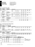
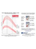
Transcription of Hose Selection CHART 1. Hose Flow Rate vs. Pressure Drop ...
1 EATON Weatherhead Hose Assembly Master Catalog W-HYOV-MC002-E2 March 200811 TECHNICAL DATAHOSE ASSEMBLY EQUIPMENT ADAPTERS & TUBE HOSE ENDS ACCESSORRIES & ASM BLY INSTRUCTIONSSPECIALTY HOSE HIGH Pressure HOSELOW & MEDIUM Pressure HOSEAPPLICATION DATA WARNINGFor important safety infor-mation concerning hose Selection , see page 4 of this are several factors which affect Selection of a hose sized such that it will provide the desired rate of flow at the required Pressure ; these are: Hose size Hose length Hose ends Material conveyed Bends Static head pressureHose SizeUndersized Pressure lines produce excessive Pressure drop with attendant energy loss and heating, and undersized suction lines cause cavitation at the pump inlet. Oversized hose assemblies, on the other hand, are excessively costly and generally too selecting hose for hydraulic systems, the following empirical values can be used to achieve minimum Pressure drop consistent with reasonable hose size (see CHART 2):Velocity of Pressure lines 7 to 15 of short Pressure lines to 20 of suction lines 2 to 5 use CHART 2, lay a straight-edge across the CHART as shown by the dotted line.
2 To minimize Pressure drop , always use the next larger size hose shown if the line passes between sizes LengthChart 1 gives the Pressure drop in different-sized hoses based on hoses of 100-foot length, and is based on water as the material conveyed. For hoses of a different length, these values must be corrected. For example, a 100-foot length of 1/2" hose causes a Pressure drop of 100 at a flow rate of 10 If the hose in question is 50 feet long, the Pressure drop derived from CHART 1 must be corrected by multiplying the value by the ratio of the actual length to 100 feet, or 50/100, or Therefore, the actual Pressure drop caused by a 50-foot length of 1/2" hose, at a flow rate of 10 , is 50 ( x 100 = 50 ).Hose Ends and Fluid ConveyedIn most cases, the end fitting openings are slightly smaller than the hose itself. However, this varies widely with hose end designs from full-flow ends which have the same as the hose, down to as much as 1/8" smaller than the hose bore.
3 To allow for this, assume a 10-to-15% greater flow rate than actually measured in the system when deter-mining Pressure 1 is based on water as the material conveyed, and for other fluids it is necessary to correct for the difference in specific gravity and viscosity. CHART 3 lists common fluids, their specific gravities, viscosi-ties, and corresponding correction determine the Pressure drop for a specific fluid, first determine the Pressure drop from CHART 1 for the hose length then divide this by the correction factor found in CHART example, the 50-foot length of 1/2" hose just de-scribed had a Pressure drop of 50 at a flow of 10 of water. To determine the Pressure drop if #2 fuel oil is the material conveyed, divide by (from CHART 3)..50 = Pressure drop . If, on the other hand, the material conveyed is Type #3 gasoline, the Pressure drop would be 50 = 42 2. Hose Flow CapacityHose SelectionCHART 1. Hose Flow Rate vs.
4 Pressure DropEATON Weatherhead Hose Assembly Master Catalog W-HYOV-MC002-E2 March 200812 APPLICATION DATALOW & MEDIUM Pressure HOSEHIGH Pressure HOSE SPECIALTY HOSE ACCESSORRIES & ASM BLY INSTRUCTIONS ADAPTERS & HOSE ENDSHOSE ASSEMBLY EQUIPMENT TECHNICAL DATACHART 4. Resistance of 90 BendsCHART 3. Fluid Flow Correction FactorsHose Selection WARNINGFor important safety infor-mation concerning hose Selection , see page 4 of this a hose of a given length is bent, the Pressure drop will increase by some definite sharper the bend and the smaller the radius of bend the greater the Pressure drop . The effect of a bend may be neglected if it is slight or if there are but few bends in a long length of hose. This is because the additional Pressure drop caused by these bends is not signifi-cant when compared to the total Pressure , a dock hose may have four sharp 90 bends in a 25-foot length, and if Pressure drop is important, these bends must be con-sidered because they con-stitute a significant portion of the overall Pressure curves in CHART 4 show the effects of resistance due to 90 bends.
5 This data can also be used as a guide for smooth bends less or greater than 90 . For example, a 45 bend has about 4/10 the resistance of a 90 : Determine the equivalent length, in terms of hose inside diameters, of a 90 and a 180 bend whose relative radii are 12 : Referring to the total resistance curve, the equivalent length for a 90 bend is hose diameters. The equialent length of a 180 bend is diameters for one 90 bend, diameters for resistance due to length, and 2 diameters for bend resistance. Adding these , , and 2 = diameters for a 180 bend.* Note that this loss is less than the sum of losses through two 90 bends separated by Head PressureStatic head is the differ-ence in height between the inlet and outlet ends of a hose. Before using CHART 1, it is necessary to correct for static head Pressure because the values in CHART 1 are Pressure losses due to friction correct for static head Pressure , the difference in height is determined and multiplied by to convert the head to an equivalent Pressure in PSI (one foot of water exerts PSI Pressure ).
6 If the inlet is higher than the outlet, the Pressure equivalent is added to the pump Pressure . If the outlet is higher than the inlet, the Pressure equivalent is subtracted from the pump Pressure . In both cases, it is assumed that the pump Pressure is the Pressure available at the inlet end and that the pump is outside of the hose DesignHose should not be twisted or put in torsion either during the installation or while in service. Sharp or excessive bends may cause the hose to kink or sure to allow enough slack to provide for changes in length which will occur when Pressure is applied. This change in length can vary from +2% to -4%.Design the installation so the hose assembly is acces-sible for inspection and easy radius is important. A good working rule is that the minimum bend radius should be five or more times the dimension of the hose.* In a continuous bend of 180 degrees the second 90 degree bend produces approximately one-half the resistance of the first bend.