Transcription of HOSHIZAKI TECHNICAL SUPPORT TECH -TIPS
1 HOSHIZAKI TECHNICAL SUPPORT TECH -TIPS _____ Rodd Burger HOSHIZAKI America, Inc. Volume 207 Writer/Editor 618 Hwy. 74 South Oct 13, 2003 Peachtree City, GA 30269 Ph: (800) 233-1940 Fax: (800) 843-1056 E-mail: _____TROUBLESHOOTING 3 BEEPS (Part 1) By Lonnie Clayton In this article we will assist technicians in troubleshooting the 3 beep error code.
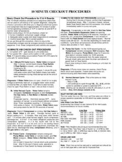
2 The 3-beep error is the result of two consecutive long freeze cycles. The length of the maximum freeze cycle is determined by the position of DIP switches 9 & 10. Settings for these DIP switches are shown below. When the freeze cycle has reached the maximum freeze time and the float switch has not opened to terminate the freeze cycle the control board will automatically initiate a harvest cycle. After completion of harvest the unit will continue into the next freeze cycle.
3 If the next freeze cycle reaches the maximum freeze time the back up timer will again initiate the harvest cycle. This is when the safety alarm engages and locks the machine out on a manual reset, 3-beep audible alarm. The freeze cycle on HOSHIZAKI KM ice machines is controlled by water level. As the ice is being formed on the evaporator the level of water in the reservoir drops. Once it has dropped low enough to open the float switch the freeze cycle is terminated and the pump out or harvest cycle begins.
4 During normal operation the water level must drop before the unit will go into harvest. In the case of the 3-beep alarm, the harvest cycle was not initiated by the float switch opening. Before beginning our troubleshooting, we must reset the control board. On the control board next to the yellow and orange LED there is small alarm reset button. Press and release this pin while the board is beeping. Pressing this pin with the power off will not reset the alarm. Once reset we can troubleshoot the three-beep error.
5 Many times the reason for erratic operation is caused by a dirty or scaled machine. Before beginning your troubleshooting please make sure the machine has been thoroughly cleaned. Evaporators, water valve, float switch all need to be cleaned before proceeding into the trouble-shooting phase. For more detailed information on cleaning, see Tech Tip Vol. 186. Now that the machine and float switch are clean, we need to confirm component operation. Since the float switch actually sends the unit into harvest, it will be first on the list.
6 Float Switch: To check the float, remove it from the machine and check the continuity of the switch. Remove the float switch plug from the K5 connector on the board. With your ohmmeter on the plug wires and the float in the down position the switch is open, when it is up or the float turned upside down, the switch is closed. If the switch is closed or open all the time, no matter what position the float is in, the float switch needs replacing. The DIP SW. 9 DIP SW.
7 10 MAX. FREEZE TIME ON ON 75 Min/50hz 60 Min/60hz ON OFF 70 Min OFF ON 50 Min OFF OFF 60 Min number one cause for failure of float switches is scale. Water inlet Valve: This valve should be completely closed during our freeze cycle. To check this part pull the small hose off the water valve outlet going to the evaporator section. No water should be flowing from this valve during the freeze cycle. If water is by passing the valve, disassemble and clean/replace if necessary.
8 See SB01-0009 for more info on water valve re-building. Control Board: Test the control board, float switch operation. After 5 minutes of freeze drain the water out of the reservoir. When the water has drained the float switch will open and the control board will terminate the freeze cycle and initiate the harvest or pump out cycle. If the freeze cycle does not terminate, remove the K5 connection to the board. If the unit still does not go into harvest, the control board is defective.
9 Note: It is important to confirm what portion of the cycle the board is in. With E style control boards this can be done by confirming which LED lights are energized. When the board is in harvest, LED 1, 4 and 2 should be energized. When the control board goes into the freeze cycle LED 1 will energize. If you are working on a unit with an earlier control board this check can be done using a volt meter. When the unit is in harvest you will read 115 VAC at the pink wire and when it is in freeze the black and red wires will be energized.
10 Water pump: The water pump itself can be easily tested by putting the unit in wash. We must however also confirm the operation of the water pump in conjunction with the control board. When the unit begins the freeze cycle, the water pump and condenser fan motor should energize on self-contained units. (Remote units the condenser fan starts with the compressor.) If the water pump fails to come on check voltage from the control board K1 connector, red wire, we should see 110 volts.